6 if out (j2) – Comtech EF Data SFC1800A User Manual
Page 69
SFC1800A Synthesized Frequency Upconverter
Rear Panel Interfaces
TM111 – Rev. 1.0
5-3
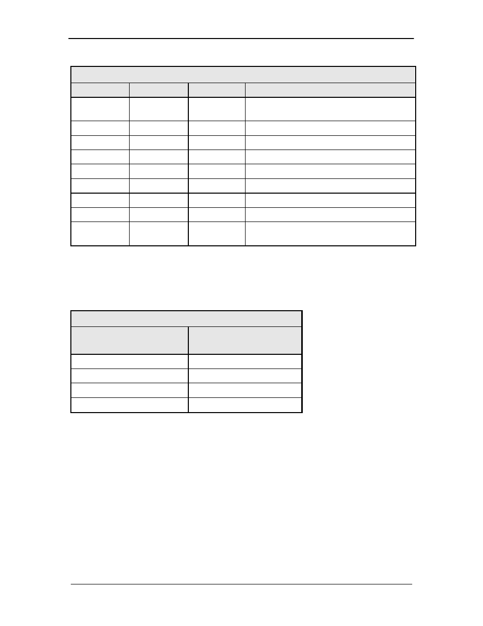
Table 5-2. J8 – Operator Serial I/O Port – D-Sub 9-Pin Female Connector
Pin No.
Signal
I/O
Description
1
RX_485 – A
RX_232
I
Inverted RS-485 Receive
RS-232 receive
2
TX_485-B
O
Non-Inverted RS-485 transmit
3
RX_485-B
I
Non-Inverted RS-485 receive
4
DTR
N.A.
Connected internally to Pin 6-DSR
5
GND
N.A.
Ground
6
DSR
N.A.
Connected internally to Pin 4-DTR
7
RTS
N.A.
Connected internally to Pin 8-CTS
8
CTS
N.A.
Connected internally to Pin 7-RTS
9
TX_485 – A
TX_232
O
Inverted RS-485 Transmit
RS-232 Transmit
If the RS-232 option is chosen, an adapter must be used between J8 and the serial cable to the
DTE. One end of the adapter will be a DB-9-M connector, which plugs into J8 on the upconverter
back panel. The other end will be a DB-9-F connector, which plugs into the PC serial port or
dumb terminal. The pinout is given in Figure 5-3.
Table 5-3. – RS-232 Adaptor – Operator Serial I/O Port
Pin No.
DB-9 Male to Upconverter J8
Pin No.
DB-9 Female to DTE
1
3
5
5
9
2
2,3,4,6,7,8
N.A.
5.6 IF Out (J2)
The IF Out Connector (J2) is a 75 Ohm BNC-F Connector. Outputs are within 50 – 90 MHz for
standard units and 100 – 180 MHz for units equipped with 140 MHz.