7 terminal (j6), 8 ethernet (j9) – Comtech EF Data SFC1800A User Manual
Page 70
Rear Panel Interfaces
SFC1800A Synthesized Frequency Upconverter
5-4
TM111 - Rev. 1.0
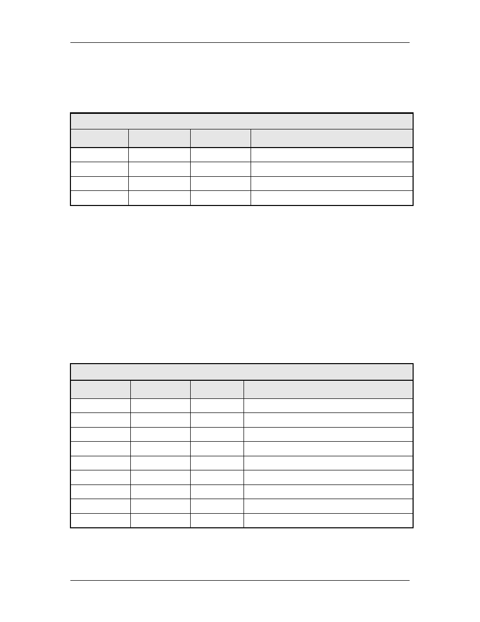
5.7 Terminal (J6)
The Terminal Port allows for complete control and monitoring of all Upconverter parameters and
functions via an RS-232 Serial Interface. The interface comes configured as a DCE device. The
pinout is given in Table 5-4.
Table 5-4. J8 – Terminal Port – D-Sub 9-Pin Female Connector
Pin No.
Signal
I/O
Description
2
TX_232
O
RS-232 transmit
3
RX_232
I
RS-232 receive
5
GND
N.A.
Ground
1, 4, 6, 7, 8, 9
N.A.
N.A.
No Connect
5.8 Ethernet (J9)
The Ethernet connector can be used for monitor & control functions of the upconverter. The
physical interface is a standard RJ-45 connector.
5.9 Equipment RS-485 (J10), Standard Backward Compatible Interface
The Equipment Multi-Drop, Full-Duplex, Bi-directional RS-485 Interface (J10) allows
communication between converters. Because the RS-485 Interface uses a master/slave
(talker/listener) configuration, the converter that is designated as the backup will automatically be
established as the master. Under normal RS-485 protocol, the master will poll a specific slave by
address and only then will the slave unit respond. The swapping of Transmit Data and Receive
Data is accomplished in the inter-converter cables, as the hardware interface is identical for all
converters. Refer to Table 5-5 for the connector pinout.
Table 5-5. J6 – Equipment RS-485 Interface - D-Sub 9-Pin Female Connector
Pin No.
Signal
I/O
Description
1
GND
N.A.
Ground
2
I2C_SCL
O
I2C Clock
3
N.C.
N.A.
No Connect
4
TX_485-B
O
Inverted RS-485 transmit
5
TX_485-A
O
Non-Inverted RS-485 transmit
6
I2C_SDA
I/O
I2C Data
7
N.C.
N.A.
No Connect
8
RX_485-B
I
Inverted RS-485 receive
9
RX_485-A
I
Non-Inverted RS-485 receive