1 real time clock (rtc), 14 jtag interface, 15 interrupts – Artesyn ATCA-9405 Installation and Use (May 2014) User Manual
Page 86: 14 jtag interface 4.15 interrupts, Table 4-11, P2020 i2c bus assignment, Service processor
Service Processor
ATCA-9405 Installation and Use (6806800M71G)
86
I2C bus 1 is used to connect to a boot sequencer memory and the SPD PROM device of the
DDR3 memory module. The boot sequencer can be optionally used for initialization of the
P2020.
I2C bus 2 is connected to an onboard RTC (DS1337).
4.13.1 Real Time Clock (RTC)
The blade provides an I2C™-bus-compatible real-time clock type DS1337 from Maxim. This
device contains a real-time clock/calendar and 31 bytes of static random access memory
(SRAM). The real-time clock/calendar provides seconds, minutes, hours, day, date, month, and
year information. The end of the month date is automatically adjusted for months with fewer
than 31 days, including corrections for leap year up to the year 2100. The clock operates in
either the 24hr or 12hr format with an AM/PM indicator. A battery socket is provided on the
board to backup the RTC power supply.
4.14 JTAG Interface
The IEEE 1149.1 compliant JTAG boundary scan interface of the P2020 is connected to an
onboard 16-pin COP header to support a processor emulator for board debug. For connector
pin out details, refer to
.
4.15 Interrupts
The Service Processor is responsible for handling of infrastructure related interrupts.
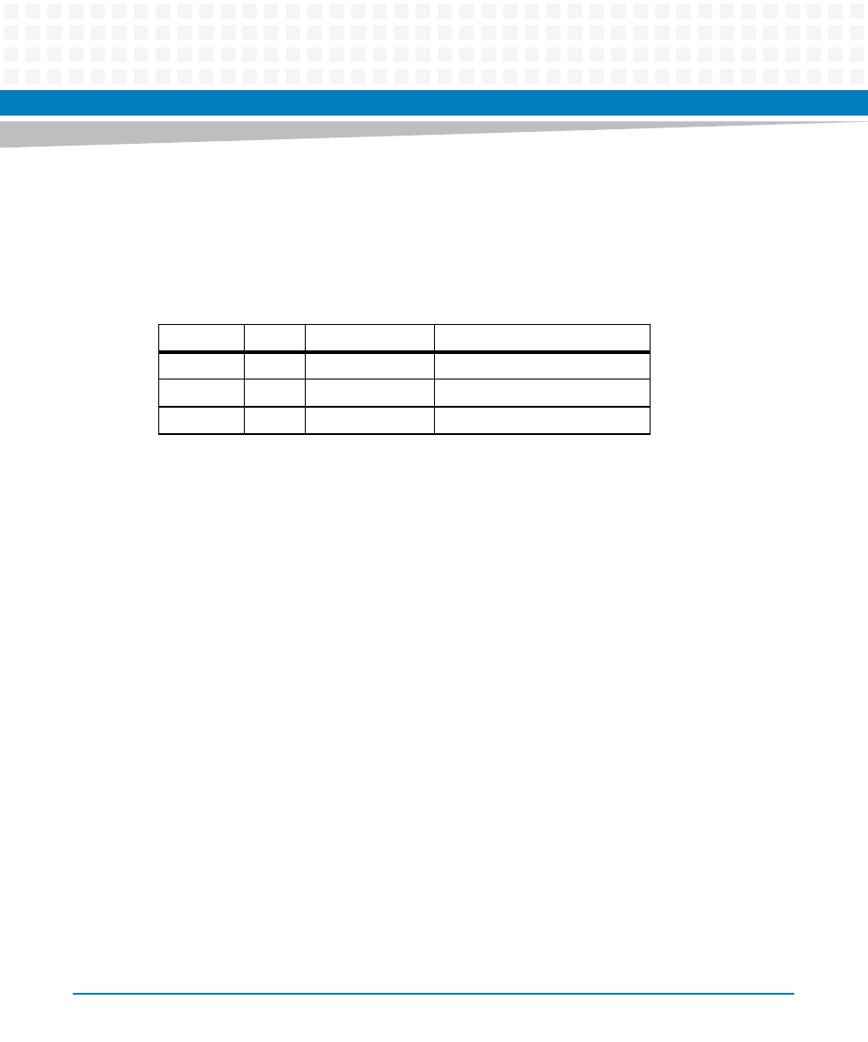
Table 4-11 P2020 I2C Bus Assignment
Address
Bus
Component
Function
0xA0
1
AT24C64C
Boot Sequencer ROM
0xA2
1
SPD
DIMM Module SPD PROM
0xD0
2
DS1337U+
Real Time Clock