Table 2-4, Settings for switch sw2 (for debugging only), Table 2-5 – Artesyn ATCA-9405 Installation and Use (May 2014) User Manual
Page 36: Settings for switch sw3, Setup
Setup
ATCA-9405 Installation and Use (6806800M71G)
36
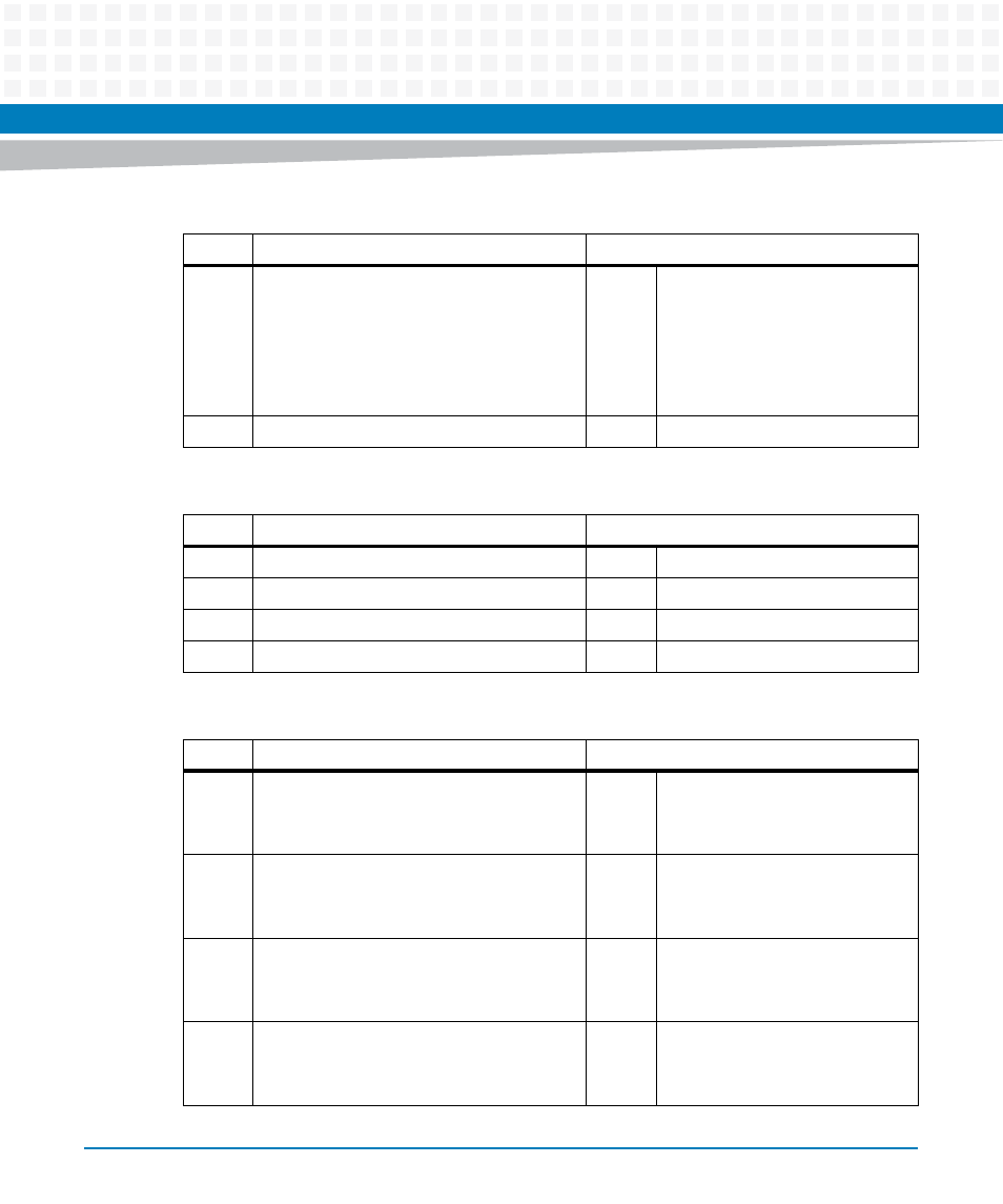
SW1-3
Debug Header Boot Select
This switch overrides selection done via
SW1-1 and SW1-2.
OFF = Boot from SPI Boot Flash (TSOP
devices)
ON = Boot from SPI Debug Header
OFF
Boot from TSOP SPI Flash
SW1-4
Reserved
OFF
Do not change
Table 2-4 Settings for Switch SW2 (for debugging only)
Switch
Description
Default
SW2-1
Reserved
OFF
Do not change
SW2-2
Reserved
OFF
Do not change
SW2-3
Reserved
OFF
Do not change
SW2-4
Reserved
OFF
Do not change
Table 2-5 Settings for Switch SW3
Switch
Description
Default
SW3-1
Enable E10-USB Emulator for H8S
OFF = Disabled
ON = Enabled
OFF
E10-USB Emulator disabled
SW3-2
Enable H8S Programming via Debug Console
OFF = Disabled
ON = Enabled
OFF
H8S programming disabled
SW3-3
Manual Payload Power Enable for Blade
OFF = IPMI controlled power enable for blade
ON = Manual power enable for blade
OFF
IPMI controlled power enabled
SW3-4
Manual Payload Power Enable for RTM
OFF = IPMI controlled power enable for RTM
ON = Manual power enable for RTM
OFF
IPMI controlled power enabled
Table 2-3 Settings for Switch SW1 (continued)
Switch
Description
Default