15 power supply, Table 3-6, Packet processor interrupts – Artesyn ATCA-9405 Installation and Use (May 2014) User Manual
Page 69: Packet processor
Packet Processor
ATCA-9405 Installation and Use (6806800M71G)
69
Up to 16 GPIO pins are provided by the CN6880 to connect external interrupts with the central
interrupt unit. Each GPIO pin can be programmed to be a level-sensitive interrupt pin or an
edge-triggered interrupt pin.
All interrupt sources from the packet processor domains are directly connected to the
GPIO[5:1] inputs of the associated Packet Processor.
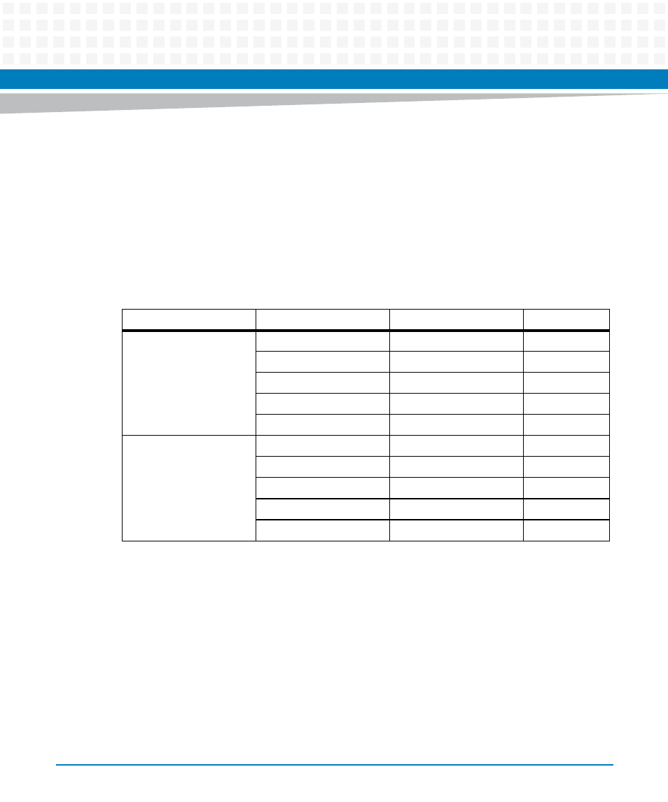
The following table lists all interrupt sources of the packet processor domains and how the
interrupts are routed on the board:
3.15 Power Supply
ATCA-9405 supports software controlled power-down and power-on sequence for the two
Packet Processor units as described in
Table 3-6 Packet Processor Interrupts
Interrupt Source
Interrupt Name
Usage
IRQ Line
PP1
PP1_DDR0_EVENT_N
DIMM1 Thermal Event
PP1_GPIO2
PP1_DDR1_EVENT_N
DIMM2 Thermal Event
PP1_GPIO3
PP1_DDR2_EVENT_N
DIMM3 Thermal Event
PP1_GPIO4
PP1_DDR3_EVENT_N
DIMM4 Thermal Event
PP1_GPIO5
PP1_ETH_INT_N
88E1512 PHY Interrupt
PP1_GPIO1
PP2
PP2_DDR0_EVENT_N
DIMM1 Thermal Event
PP2_GPIO2
PP2_DDR1_EVENT_N
DIMM2 Thermal Event
PP2_GPIO3
PP2_DDR2_EVENT_N
DIMM3 Thermal Event
PP2_GPIO4
PP2_DDR3_EVENT_N
DIMM4 Thermal Event
PP2_GPIO5
PP2_ETH_INT_N
88E1512 PHY Interrupt
PP2_GPIO1