3 connector pin assignment, 1 face plate connectors, Table 2-7 – Artesyn ATCA-9405 Installation and Use (May 2014) User Manual
Page 39: Usb connector pin-out, Table 2-8, Ethernet connector pin-out, Setup, Ethernet ports
Setup
ATCA-9405 Installation and Use (6806800M71G)
39
2.3.3
Connector Pin Assignment
2.3.3.1
Face Plate Connectors
for the face plate layout.
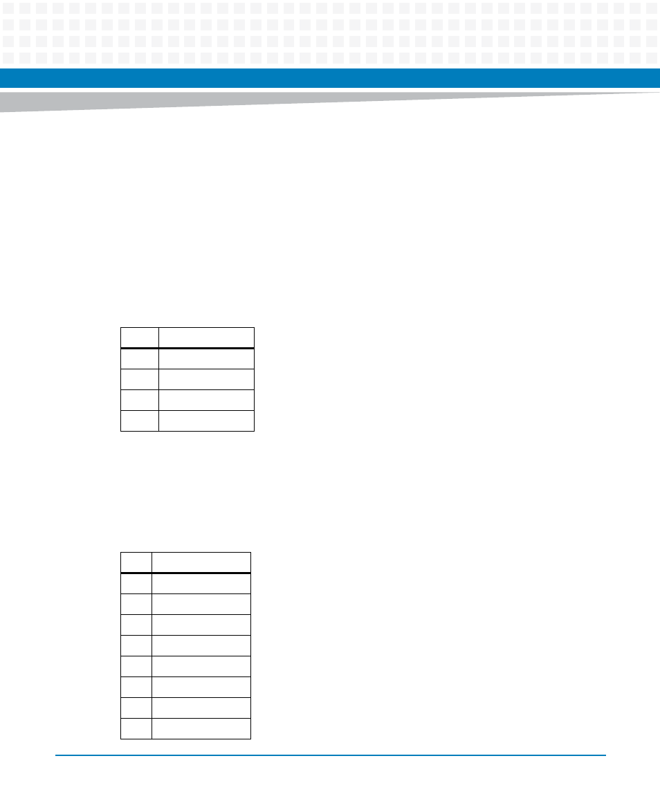
2.3.3.1.1 USB Port
One standard USB Type-A connector for access to the USB interface of the Service Processor is
available at the face plate.
2.3.3.1.2
Ethernet Ports
Two shielded RJ45 connectors with integrated transformers for 10/100/1000Base-T Ethernet
are available at the front panel.
Table 2-7 USB Connector Pin-out
Pin
Signal
1
VCC_USB
2
D-
3
D+
4
GND
Table 2-8 Ethernet Connector Pin-out
Pin
Signal
1
BI_DA+
2
BI_DA-
3
BI_DB+
4
BI_DC+
5
BI_DC-
6
BI_DB-
7
BI_DD+
8
BI_DD-
This manual is related to the following products: