4 vga-7360 module connector, Table 3-2, Vga-7360 module connector pinout – Artesyn ATCA-7365-CE Installation and Use (May 2014) User Manual
Page 76: Table 3-3, Face plate vga connector signals, Controls, indicators, and connectors
Controls, Indicators, and Connectors
ATCA-7365-CE Installation and Use (6806800L73J)
76
3.2.3.4
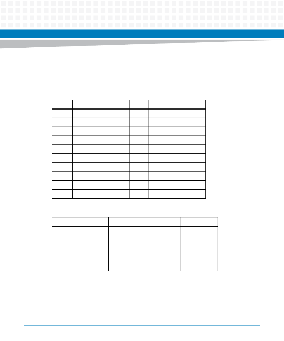
VGA-7360 Module Connector
Several variants of ATCA-7365 support the VGA-7360 module. For more information, refer to
.
Table 3-2 VGA-7360 Module Connector Pinout
Pin
Signal
Pin
Signal
1
GND
2
GND
3
+1.8V
4
PCIE_TX+
5
+1.8V
6
PCIE_TX-
7
GND
8
GND
9
+3.3V
10
PCIE_RX+
11
+3.3V
12
PCIE_RX-
13
GND
14
GND
15
+5V
16
PCIE_CLK100MHz+
17
PCIE_RST#
18
PCIE_CLK100MHz-
19
GND
20
GND
Table 3-3 Face Plate VGA Connector Signals
Pin
Signal
Pin
Signal
Pin
Signal
11
-
6
GND
1
RED
12
SDA
7
GND
2
GREEN
13
HSYNC
8
GND
3
BLUE
14
VSYNC
9
+5V
4
-
15
SCLK
10
GND
5
GND