22 telecom clock supervision registers, 1 telecom clocking status registers, Table 6-75 – Artesyn ATCA-7365-CE Installation and Use (May 2014) User Manual
Page 213: Telecom backplane clocking status register, Table 6-76, Telecom backplane clocking latch register, Table 6-77, Telecom ch1_clk1a clock period msb register, Maps and registers

Maps and Registers
ATCA-7365-CE Installation and Use (6806800L73J)
213
6.4.22 Telecom Clock Supervision Registers
6.4.22.1 Telecom Clocking Status Registers
The telecom backplane clocking status register indicates when the backplane input clock
signals are toggling.
The Clock period of CH1_CLK1A is measured periodically. The result of the measurement
(number of LPC clock cycles) is latched with a write access to the Telecom Backplane Clocking
Latch Register. The 16 bit value is stored in the registers Telecom CH1_CLK1A clock period MSB
Register and Telecom CH1_CLK1A clock period LSB Register . When the clock is static or the
period is higher than a 16 bit value the result is always 0xFFFF.
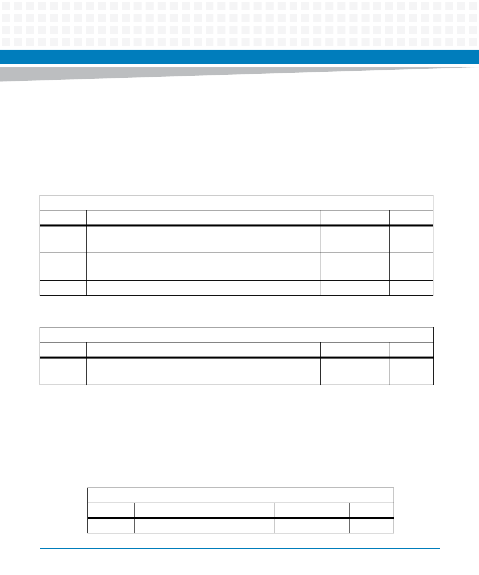
Table 6-75 Telecom Backplane Clocking Status Register
Address Offset: 0x66
Bit
Description
Default
Access
0
0: CH1_CLK1A_IN is static or period is not in the correct range.
1: CH1_CLK1A_IN is toggling
PWR_GOOD:0
LPC: r
1
0: CH1_CLK1B_IN is static or period is not in the correct range.
1: CH1_CLK1B_IN is toggling
PWR_GOOD:0
LPC: r
7:2
Reserved 0
r
Table 6-76 Telecom Backplane Clocking Latch Register
Address Offset: 0x67
Bit
Description
Default
Access
7:0
Latch clock period measurements for CH1_CLK1A and CH1_CLK1B.
Write data is discarded.
-
LPC: w
Table 6-77 Telecom CH1_CLK1A clock period MSB Register
Address Offset: 0x61
Bit
Description
Default
Access
7:0
MSB of CH1_CLK1A clock period
PWR_GOOD: 0xFF
LPC: r
