3 connectors, 1 ethernet connector, Figure 3-6 – Artesyn ATCA-7365-CE Installation and Use (May 2014) User Manual
Page 73: Location of ethernet connector, Figure 3-7, Ethernet interface connectors pinout, Controls, indicators, and connectors
Controls, Indicators, and Connectors
ATCA-7365-CE Installation and Use (6806800L73J)
73
3.2.3
Connectors
The blade provides the following connectors at its face plate:
1x Ethernet
1x Serial
2x USB
VGA Connector (supported on
ATCA-7365-24GB-V-CE)
3.2.3.1
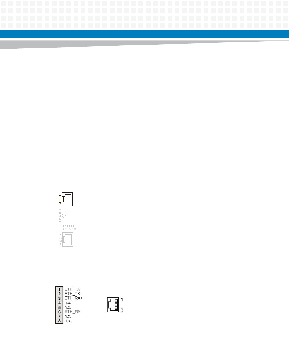
Ethernet Connector
The blade provides one Ethernet 1000Base-T interface connector at its face plate. It is intended
for blade configuration and constitutes, besides the two AdvancedTCA Base interfaces, a third
Ethernet interface to access the blade. The location of the Ethernet connector is shown in the
following figure.
The pinout of the connector is as follows.
Figure 3-6
Location of Ethernet Connector
Figure 3-7
Ethernet Interface Connectors Pinout