2 serial interface connector, Figure 3-8, Location of serial connector – Artesyn ATCA-7365-CE Installation and Use (May 2014) User Manual
Page 74: Figure 3-9, Serial interface connector pinout, Serial interface connector
Controls, Indicators, and Connectors
ATCA-7365-CE Installation and Use (6806800L73J)
74
3.2.3.2
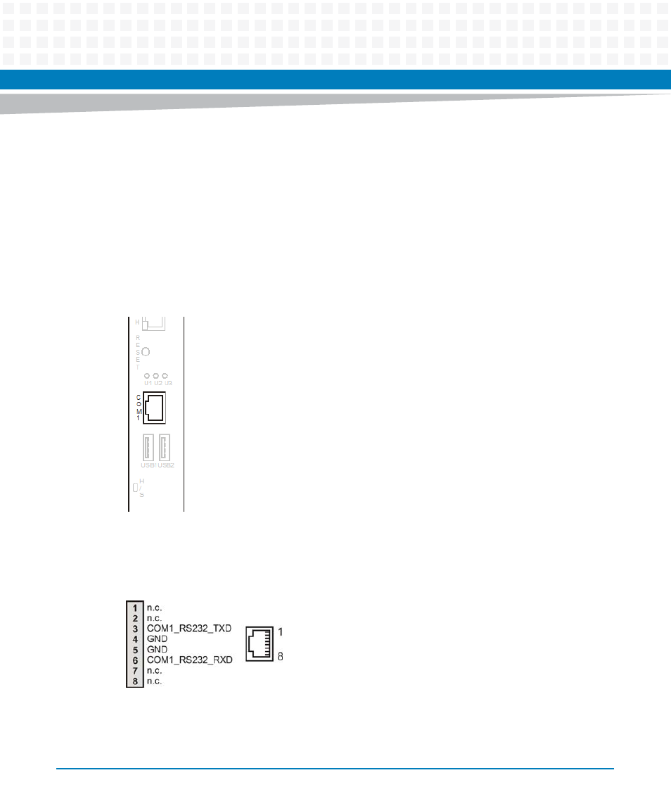
Serial Interface Connector
The blade provides one RS-232 serial interface connector at its face plate. It is of type RJ-45 and
corresponds to the physical serial interface port 1. By default, the BIOS maps this interface to
the serial interface COM1. The on-board switch 2-1 allows to swap COM1 with COM2 and thus
make COM2 accessible via the face plate connector instead. Note that the BIOS serial
redirection feature uses COM1 as access interface. Therefore swapping the serial interfaces via
SW2-1 also changes the serial connector that you need to access to make use of the serial
redirection feature. The location of the connector is shown in the following figure.
The pinout of the serial interface connector is shown below.
Figure 3-8
Location of Serial Connector
Figure 3-9
Serial Interface Connector Pinout