beautypg.com

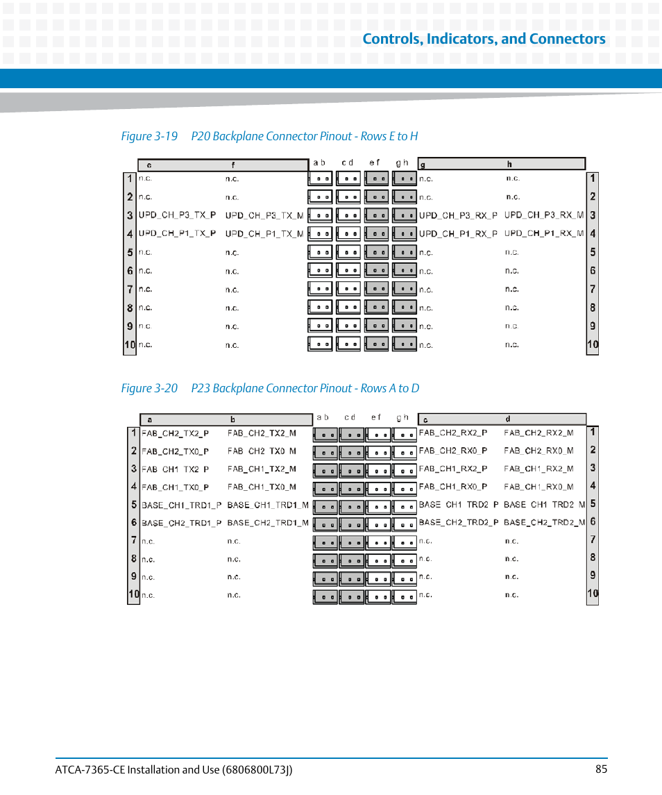
Figure 3-19, P20 backplane connector pinout - rows e to h, Figure 3-20 – Artesyn ATCA-7365-CE Installation and Use (May 2014) User Manual

Page 85: P23 backplane connector pinout - rows a to d, Controls, indicators, and connectors

Figure 3-19, P20 backplane connector pinout - rows e to h, Figure 3-20 | P23 backplane connector pinout - rows a to d, Controls, indicators, and connectors | Artesyn ATCA-7365-CE Installation and Use (May 2014) User Manual | Page 85 / 294 Figure 3-19, P20 backplane connector pinout - rows e to h, Figure 3-20 | P23 backplane connector pinout - rows a to d, Controls, indicators, and connectors | Artesyn ATCA-7365-CE Installation and Use (May 2014) User Manual | Page 85 / 294