Testbench simulation behavior, Testbench simulation behavior -2 – Altera 100G Interlaken MegaCore Function User Manual
Page 83
In Arria 10 variations, the example design includes external TX PLLs. You can examine the clear text files
to view sample code that implements one possible method to connect external PLLs to the
100G Interlaken IP core.
The Arria 10 example design packs six Interlaken lanes in a transceiver block, and connects all of the
channels in the same transceiver block to a single ATX PLL. The IP core connects each ATX PLL to the
100G Interlaken IP core
tx_pll_locked
and
tx_pll_powerdown
ports. This simple connection model is
only one of many options available to you for configuring and connecting the external PLLs in your
100G Interlaken design.
100G Interlaken IP Core Testbench Interface Signals
on page 7-2
Running the Testbench With the Example Design
on page 7-3
100G Interlaken IP Core Testbench Interface Signals
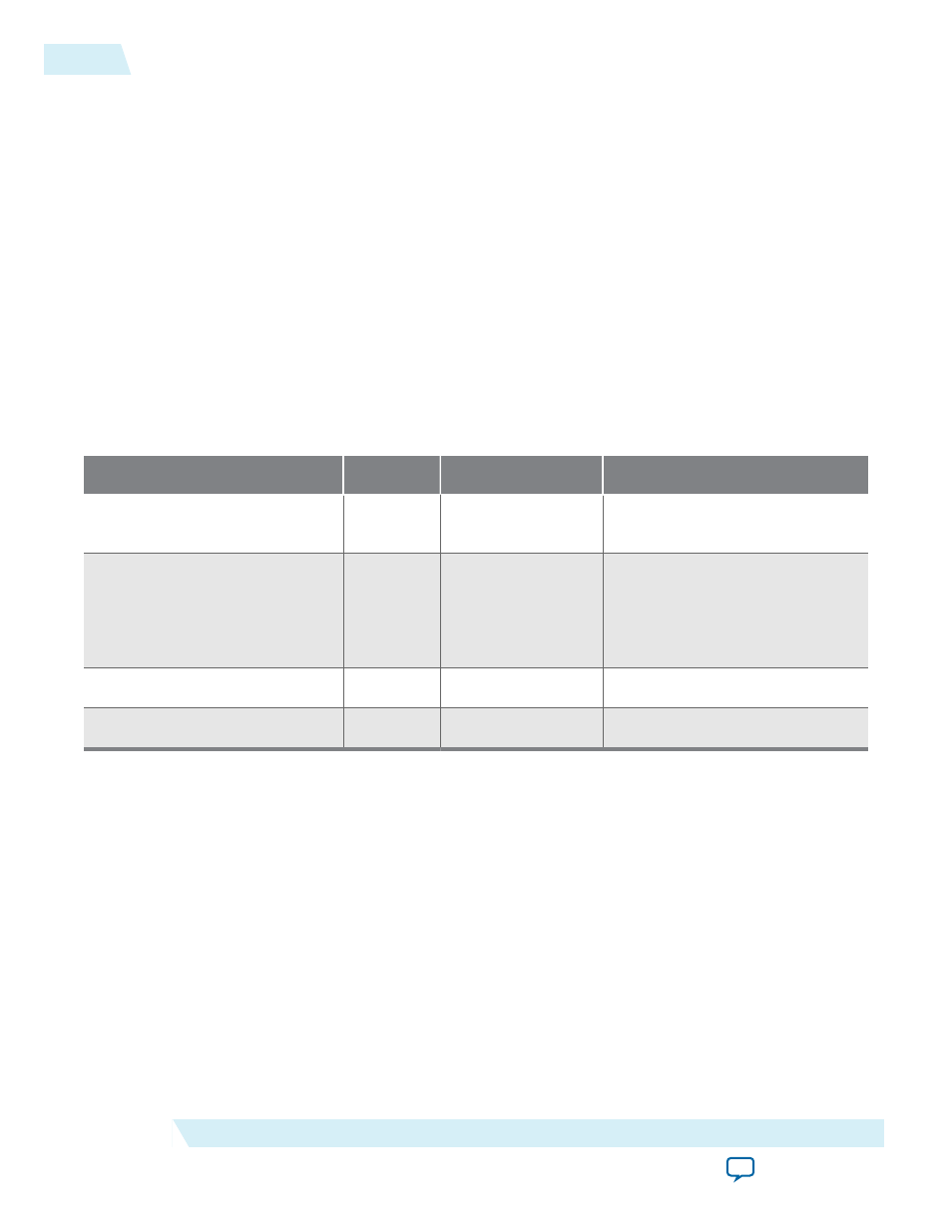
Table 7-1: 100G Interlaken IP Core TestBench Signals
Port Name
Direction
Width (Bits)
Description
clk50
Input
1
System clock input. Clock
frequency is 50 MHz.
pll_ref_clk
Input
1
Transceiver reference clock.
Drives the RX CDR PLL in Arria
10 variations, and drives both the
TX PLL and the RX PLL in other
variations.
rx_pin
Input
Number of lanes
Receiver SERDES data pin.
tx_pin
Output
Number of lanes
Transmit SERDES data pin.
Related Information
100G Interlaken IP Core Clock Interface Signals
on page 5-1
Lists the valid PLL reference clock frequencies.
Testbench Simulation Behavior
During simulation, the 100G Interlaken IP core testbench performs the following actions:
1. Resets the 100G Interlaken IP core.
2. After the reset sequence completes, sends a sequence of Interlaken packets of fixed sizes with
predefined data in the payload to the TX user data transfer interface of the IP core. This action
continues for a preset amount of time.
7-2
100G Interlaken IP Core Testbench Interface Signals
UG-01128
2015.05.04
Altera Corporation
100G Interlaken IP Core Testbench