Altera 100G Interlaken MegaCore Function User Manual
Page 79
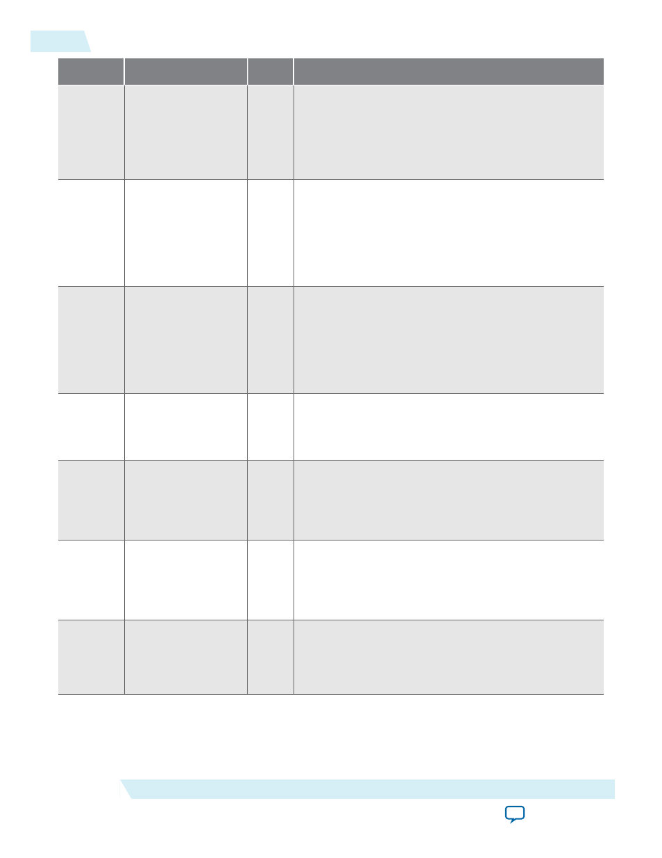
Offset
Name
R/W
Description
9'h23
CRC0
RO
4 bit counters indicating CRC errors in lanes 7,6,5,4,3,2,1,0.
These will saturate at F, and you clear them by setting bit 6
in the RESET register.
If you turn off Include diagnostic features, this register is
not available.
9'h24
CRC1
RO
4 bit counters indicating CRC errors in lanes
15,14,13,12,11,10,9,8.
These will saturate at F, and you clear them by setting bit 6
in the RESET register.
If you turn off Include diagnostic features, this register is
not available.
9'h25
CRC2
RO
4 bit counters indicating CRC errors in lanes
23,22,21,20,19,18,17,16.
These will saturate at F, and you clear them by setting bit 6
in the RESET register.
If you turn off Include diagnostic features, this register is
not available.
9'h27
SH_ERR
RO
[NUM_LANES–1:0] – Sticky flag indicating a sync header
(framing bit) error has occurred in the corresponding RX
lane since this bit was last cleared through the RESET
register.
9'h28
RX_LOA
RO
Bit [0] – Sticky flag indicating loss of RX side lane-to-lane
alignment since this bit was last cleared through the RESET
register. Typically, the IP core asserts this bit in case of a
catastrophic problem such as one or more lanes going
down.
9'h29
TX_LOA
RO
Bit [0] – Sticky flag indicating loss of TX side lane to lane
alignment since this bit was last cleared through the RESET
register. Typically, the IP core asserts this bit in case of a TX
FIFO underflow / overflow caused by a significant deviation
from the expected data flow rate through the TX PCS.
9'h30
PCS_6SEL
RO
Transceiver block selection for PCS test bus. (Factory use
only).
If you turn off Include diagnostic features, this register is
not available.
6-4
100G Interlaken IP Core Register Map
UG-01128
2015.05.04
Altera Corporation
100G Interlaken IP Core Register Map