Altera 100G Interlaken MegaCore Function User Manual
Page 36
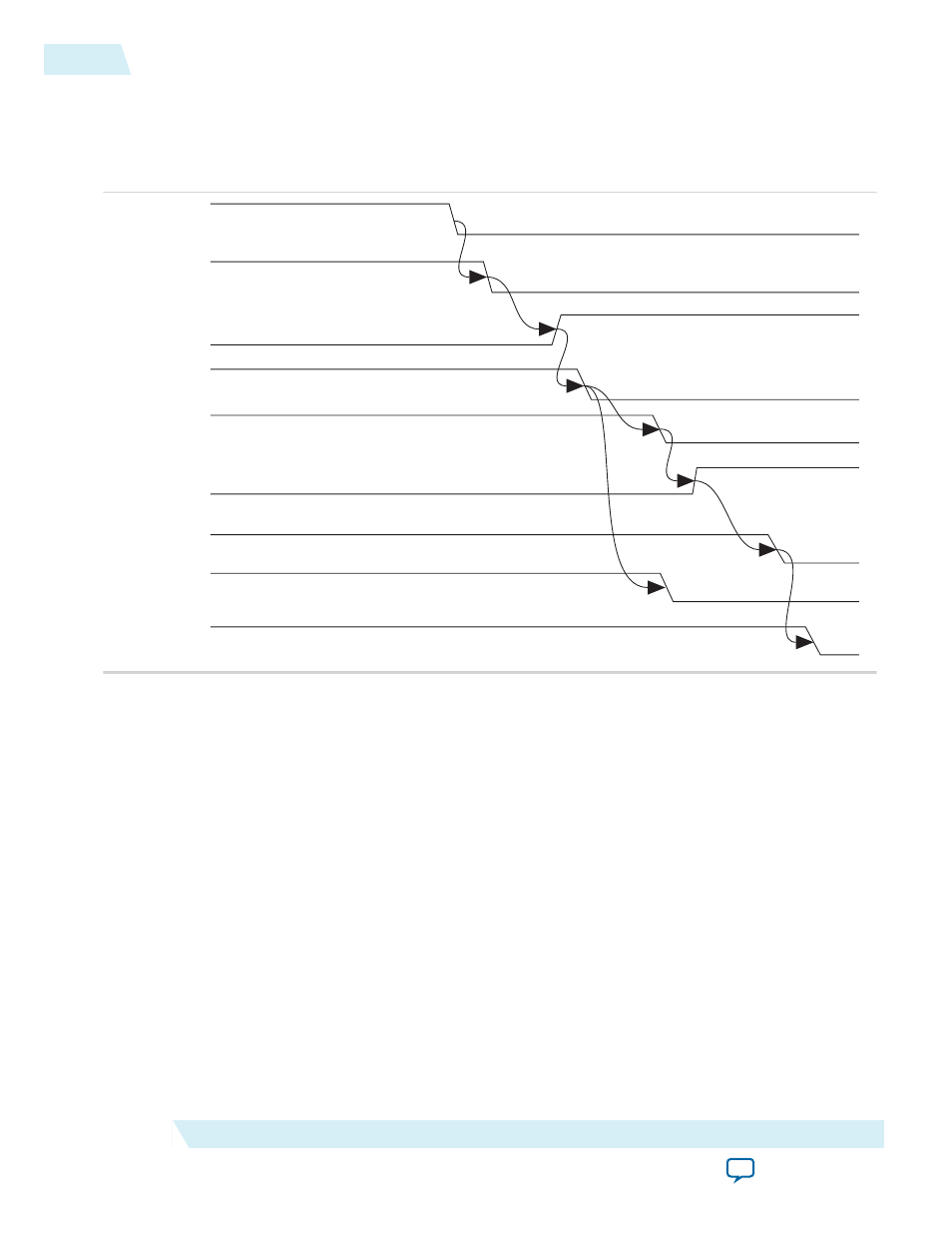
Figure 4-2: 100G Interlaken IP Core Transceiver Initialization Sequence
The internal initialization sequence implemented by the reset controller included in the 100G Interlaken
IP core. In Arria 10 devices, the
pll_locked
signal originates in the external PLL. In other devices, it
originates in the 100G Interlaken IP core itself.
reset_n
pll_pdn
pll_locked
tx_digital_rst
rx_analog_rst
rx_is_lockedtodata
rx_digital_rst
tx_usr_srst
rx_usr_srst
Following completion of the reset sequence internally, the 100G Interlaken IP core begins link initializa‐
tion. If your 100G Interlaken IP core and its Interlaken link partner initialize the link successfully, you can
observe the assertion of the lane and link status signals according to the Interlaken specification. For
example, you can monitor the
tx_lanes_aligned
,
sync_locked
,
word_locked
, and
rx_lanes_aligned
output status signals.
In Arria V GZ and Stratix V devices, after you assert the
reset_n
signal, you must wait a certain number
of
mm_clk
cycles before you can successfully access the 100G Interlaken IP core registers using the IP core
management interface.
• In hardware, you must wait 2
20
mm_clk
cycles.
• In simulation, you must wait 2
6
mm_clk
cycles.
In Arria 10 devices, the required wait time from asserting the
reset_n
signal to safely accessing the IP
core registers is a function of the internal reset controller.
Related Information
•
IP Core Reset Sequence with the Reconfiguration Controller
on page 4-7
You must wait until the required Altera Transceiver Reconfiguration Controller completes configura‐
tion of the transceivers before you assert the
reset_n
signal.
4-6
IP Core Reset
UG-01128
2015.05.04
Altera Corporation
Functional Description