Transceiver logical channel numbering, Transceiver logical channel numbering -7 – Altera 100G Interlaken MegaCore Function User Manual
Page 17
Transceiver Logical Channel Numbering
In Arria V and Stratix V devices, logical channel numbering starts from zero. The logical channel
numbering starts at the bottom of the die with logical channel 0 and continues in physical pin order
through the four ordered transceiver blocks on the same side of the device. Each data channel and TX PLL
has its own dedicated reconfiguration interface with an assigned logical channel.
In Arria 10 devices, you control the mapping of Interlaken lanes directly in the Arria 10 Native PHY IP
core that is included in the 100G Interlaken IP core.
In Arria V and Stratix V devices, you can control the logical channel assignments in the IP core. You
typically assign lanes to match the logical channel numbering. However, you can map the twelve
Interlaken lanes in a 12-lane variation to any two adjacent transceiver blocks on the same side of the
device. You can use the information in the following table to map the lanes to their default logical channel
numbering. The logical channel numbering always starts at the bottom of a transceiver block.
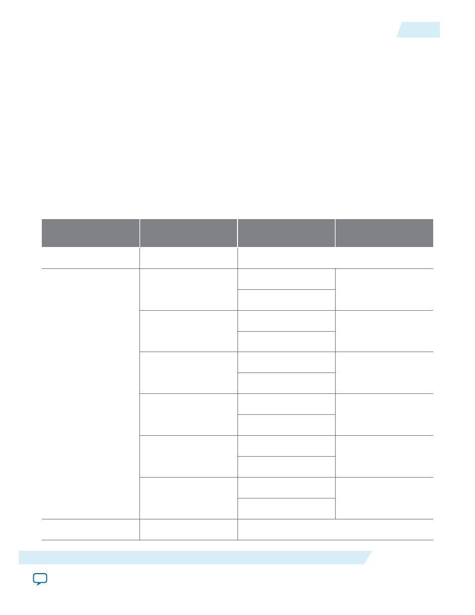
Table 2-1: Transceiver Logical Channel Numbering
The default expected mapping of logical channels to Interlaken lanes in Arria V and Stratix V devices.
Transceiver Block Number Logical Channel Number in
Device
Direction
Interlaken Lane Number in
IP Core
27
TX PLL 3
3
26
TX
23
RX
25
TX
22
RX
24
TX
21
RX
23
TX
20
RX
22
TX
19
RX
21
TX
18
RX
20
TX PLL 2
UG-01128
2015.05.04
Transceiver Logical Channel Numbering
2-7
Getting Started With the 100G Interlaken IP Core
Altera Corporation