Delta Electronics AC Motor Drive VFD-EL User Manual
Page 34
Chapter 2 Installation and Wiring|
Revision August 2008, 2ELE, V1.02
2-13
Terminal
Symbol
Terminal Function
Factory Settings (NPN mode)
ON: Connect to DCM
MI5 Multi-function
Input
5
MI6 Multi-function
Input
6
ON: the activation current is 5.5mA.
OFF: leakage current tolerance is 10μA.
+24V
DC Voltage Source
+24VDC, 50mA used for PNP mode.
DCM Digital
Signal
Common
Common for digital inputs and used for NPN
mode.
RA
Multi-function Relay output
(N.O.) a
RB
Multi-function Relay output
(N.C.) b
RC
Multi-function Relay common
Resistive Load:
5A(N.O.)/3A(N.C.) 240VAC
5A(N.O.)/3A(N.C.) 24VDC
Inductive Load:
1.5A(N.O.)/0.5A(N.C.) 240VAC
1.5A(N.O.)/0.5A(N.C.) 24VDC
Refer to Pr.03.00 for programming
+10V
Potentiometer power supply
+10VDC 3mA
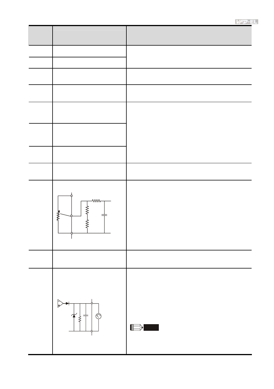
AVI
Analog voltage Input
ACM
AVI
+10V
internal circuit
AVI circuit
Impedance: 47kΩ
Resolution: 10
bits
Range:
0 ~ 10VDC/4~20mA =
0 ~ Max. Output Frequency
(Pr.01.00)
Selection: Pr.02.00,
Pr.02.09,
Pr.10.00
Set-up:
Pr.04.14 ~ Pr.04.17
ACM
Analog control signal
(common)
Common for AVI= and AFM
AFM
Analog output meter
AFM
ACM
0~10V
Max. 2mA
potentiometer
ACM circuit
internal circuit
0 to 10V, 2mA
Impedance: 47Ω
Output current
2mA max
Resolution: 8
bits
Range:
0 ~ 10VDC
Function:
Pr.03.03 to Pr.03.04
NOTE
The voltage output type for this analog signal is
PWM. It needs to read value by the movable coil
meter and is not suitable for A/D signal conversion.
NOTE: Control signal wiring size: 18 AWG (0.75 mm
2
) with shielded wire.