Delta Electronics AC Motor Drive VFD-EL User Manual
Page 118
Chapter 4 Parameters|
Revision August 2008, 2ELE, V1.02
4-75
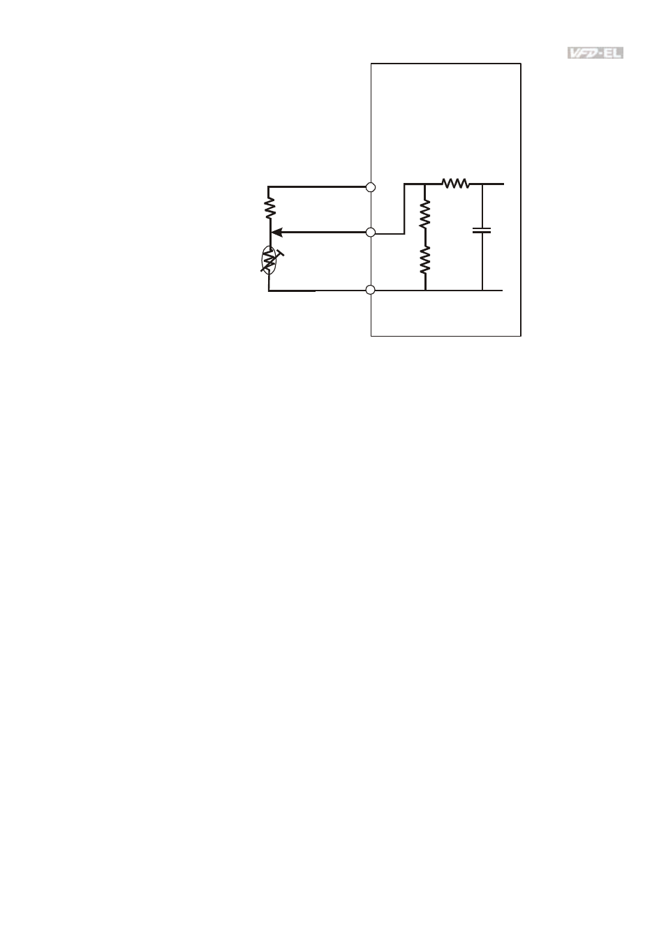
AVI
ACM
+10V
PTC
VFD-EL
47kΩ
resistor-divider
R1
internal circuit
Refer to following calculation for protection level and warning level.
1. Protection
level
Pr.07.14= V
+10
* (R
PTC1
//47K) / [R1+( R
PTC1
//47K)]
2. Warning
level
Pr.07.16= V
+10
* (R
PTC2
//47K) / [R1+( R
PTC2
//47K)]
3.
Definition:
V+10: voltage between +10V-ACM, Range 10.4~11.2VDC
R
PTC1
: motor PTC overheat protection level. Corresponding voltage level set in Pr.07.14,
R
PTC2
: motor PTC overheat warning level. Corresponding voltage level set in Pr.07.15,
47kΩ: is AVI input impedance, R1: resistor-divider (recommended value: 1~20kΩ)
Take the standard PTC thermistor as example: if protection level is 1330Ω, the voltage
between +10V-ACM is 10.5V and resistor-divider R1 is 4.4kΩ. Refer to following calculation
for Pr.07.14 setting.
1330//47000=(1330*47000)/(1330+47000)=1293.4
10.5*1293.4/(4400+1293.4)=2.38(V) ≒2.4(V)
Therefore, Pr.07.14 should be set to 2.4.
- AC Motor Drive VFD-G (183 pages)
- SMT Power Inductor SIL104R (1 page)
- Q48SB (2 pages)
- Planar DC/DC Transformer ER/ER(Plate) 22 (1 page)
- SMT Power Inductor HCB1190B (1 page)
- Series E48SR (15 pages)
- E48SR12007 (15 pages)
- SMT Power Inductor SIWC1360 (1 page)
- PFC Chokes PFC2815V Series (1 page)
- SMT Power Inductor SIB86 (1 page)
- PMC-24V050W1AA (2 pages)
- SMT Power Inductor HCB1050 (1 page)
- SMT Power Inductor HAH1330 (1 page)
- PFC Chokes PFC4120V Series (1 page)
- PFC Choke PFC3520V Series (1 page)
- SMT Power Inductor HCB1047B (1 page)
- SMT Power Inductor HAH1365 (1 page)
- SMT Power Inductor HMS1355 (1 page)
- Series S48SA (13 pages)
- E48SC (2 pages)
- SMT Power Inductor SILM106 (1 page)
- Delphi Series L48DB (2 pages)
- S48SA (13 pages)
- E36SR (2 pages)
- 3KVA (31 pages)
- SMT Power Inductor HMU1056L (1 page)
- Through Hole Power Inductors THCBR1090 (1 page)
- SMT Power Inductor SIL625 (1 page)
- SMT Power Inductor 1378(S) (1 page)
- Through Hole Power Inductors 1411 (1 page)
- Current Sense Transformers TCE1310H (1 page)
- H48SR (13 pages)
- Series E48SH (15 pages)
- Through Hole Power Inductors THAH1095 (1 page)
- Suppression Inductors LFU09V (1 page)
- SMT Power Inductor HCB0740A (1 page)
- Power Output Module DVPPS01 (2 pages)
- SMT Power Inductor SIR74 (1 page)
- L36SA (2 pages)
- 4.5V~ 5.5V (3 pages)
- Delphi Series V48SB (2 pages)
- Series S48SP (14 pages)
- Series 240W (11 pages)
- Delphi Series E24SR (15 pages)