Im 3 – Delta Electronics AC Motor Drive VFD-EL User Manual
Page 25
Chapter 2 Installation and Wiring|
2-4
Revision August 2008, 2ELE, V1.02
AVI/ACI
ACM
+
+10V
5K
3
2
1
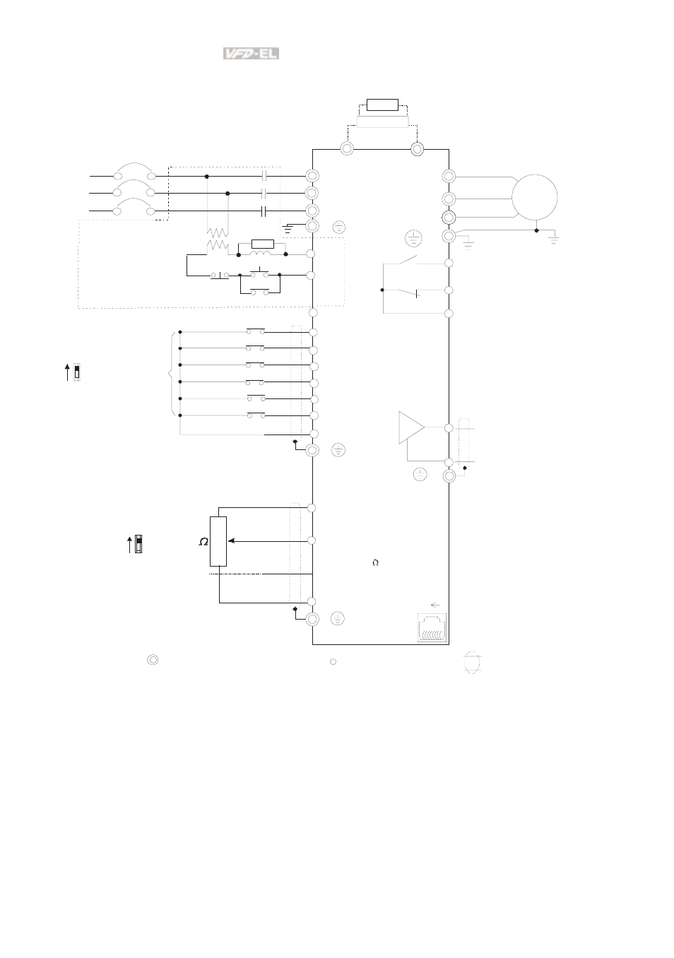
Figure 2 for models of VFD-EL Series
VFD002EL23A, VFD004EL23A/43A, VFD007EL23A/43A, VFD015EL23A/43A,
VFD022EL23A/43A, VFD037EL23A/43A
Power supply
+10V/3mA
Master Frequency
0-10V 47K
/4-20mA
Analog S ignal Common
E
Main c irc ui t (power) terminals
Control c ircuit terminals
Shielded l eads & Cable
E
R(L1)
S(L2)
Fus e/NFB(No Fuse B reaker)
SA
OFF
ON
MC
MC
RB
RC
Recommended Circui t
when power suppl y
is turned OFF by a
fault output.
If the fault occ ur s, the
contact will be O N to
turn off the power and protect the power sys tem.
R(L1)
S(L2)
E
Analog Multi-func tion Output
Terminal
Refer to c hapter 2.4 for details .
U(T1)
V(T2)
W(T3)
IM
3~
AFM
ACM
RA
RB
RC
Motor
Analog S ignal common
E
E
MI1
MI2
MI3
MI4
MI6
MI5
DCM
+24V
FWD/Stop
REV/Stop
Multi-s tep 1
Multi-s tep 2
Multi-s tep 3
Multi-s tep 4
Digital Si gnal Common
Fac tory
setting
AVI
ACI
Fac tory setting:
AVI Mode
-
RS-485
Seri al interface
1: Reserv ed
2: EV
5: SG+
6: Reserv ed
7: Reserv ed
8:
3: G ND
4: SG-
Reserv ed
8 1
NPN
PNP
Factory setting:
NPN Mode
Please refer to Figure 3
for wiring of NPN
mode and P NP
mode.
BUE
brake unit
(optional)
BR
brake resi stor
(opti onal)
Multi-function c ontact output
Refer to chapter 2.4 for details .
Factory setting is
malfunction indication
Fac tory setting: output frequency
T(L3)
T(L3)
Sw1
Sw2