B.8.3 profibus communication module (cme-pd01), B.8.3.1 panel appearance – Delta Electronics AC Motor Drive VFD-EL User Manual
Page 194
Appendix B Accessories|
Revision August 2008, 2ELE, V1.02
B-19
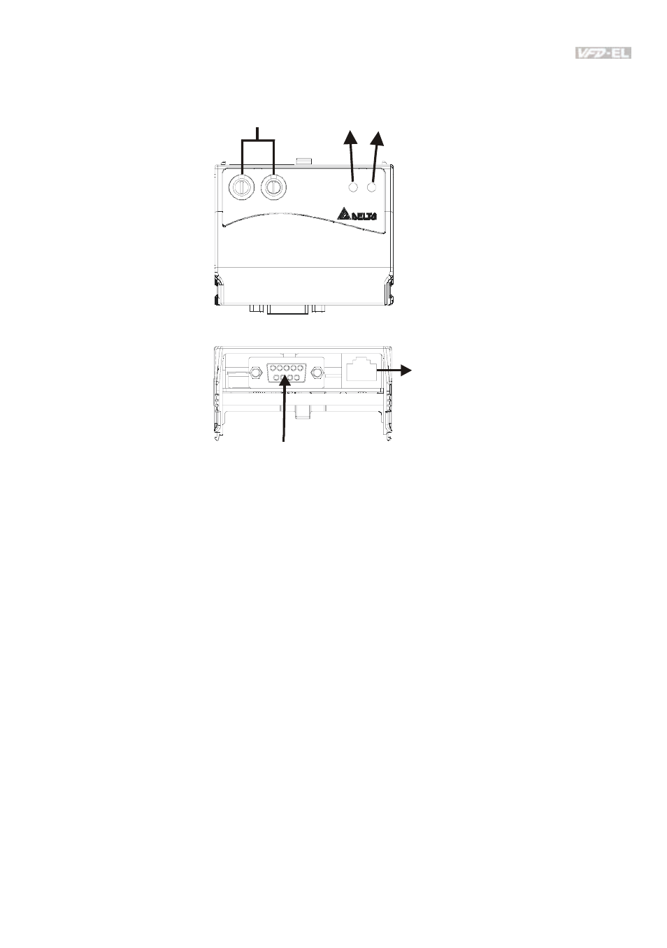
B.8.3 Profibus Communication Module (CME-PD01)
B.8.3.1 Panel Appearance
1: Reserved
2: EV
5: SG+
6: Reserved
7: Reserved
8: Reserved
3: GND
4: SG-
Profibus-DP
Interface (DB9)
RS-485 (RJ45)
ADDH ADDL
SP
NET
CME-P B01
SP LED
NET LED
Address Switches
1.
SP LED: Indicating the connection status between VFD-EL and CME-PD01.
2.
NET LED: Indicating the connection status between CME-PD01 and PROFIBUS-DP.
3.
Address Switches: Setting the address of CME-PD01 on PROFIBUS- DP network.
4.
RS-485 Interface (RJ45): Connecting to VFD-EL, and supply power to CME-PD01.
5. PROFIBUS-DP
Interface
(DB9): 9-PIN connector that connects to PROFIBUS-DP
network.
6.
Extended Socket: 4-PIN socket that connects to PROFIBUS-DP network.
- AC Motor Drive VFD-G (183 pages)
- SMT Power Inductor SIL104R (1 page)
- Q48SB (2 pages)
- Planar DC/DC Transformer ER/ER(Plate) 22 (1 page)
- SMT Power Inductor HCB1190B (1 page)
- Series E48SR (15 pages)
- E48SR12007 (15 pages)
- SMT Power Inductor SIWC1360 (1 page)
- PFC Chokes PFC2815V Series (1 page)
- SMT Power Inductor SIB86 (1 page)
- PMC-24V050W1AA (2 pages)
- SMT Power Inductor HCB1050 (1 page)
- SMT Power Inductor HAH1330 (1 page)
- PFC Chokes PFC4120V Series (1 page)
- PFC Choke PFC3520V Series (1 page)
- SMT Power Inductor HCB1047B (1 page)
- SMT Power Inductor HAH1365 (1 page)
- SMT Power Inductor HMS1355 (1 page)
- Series S48SA (13 pages)
- E48SC (2 pages)
- SMT Power Inductor SILM106 (1 page)
- Delphi Series L48DB (2 pages)
- S48SA (13 pages)
- E36SR (2 pages)
- 3KVA (31 pages)
- SMT Power Inductor HMU1056L (1 page)
- Through Hole Power Inductors THCBR1090 (1 page)
- SMT Power Inductor SIL625 (1 page)
- SMT Power Inductor 1378(S) (1 page)
- Through Hole Power Inductors 1411 (1 page)
- Current Sense Transformers TCE1310H (1 page)
- H48SR (13 pages)
- Series E48SH (15 pages)
- Through Hole Power Inductors THAH1095 (1 page)
- Suppression Inductors LFU09V (1 page)
- SMT Power Inductor HCB0740A (1 page)
- Power Output Module DVPPS01 (2 pages)
- SMT Power Inductor SIR74 (1 page)
- L36SA (2 pages)
- 4.5V~ 5.5V (3 pages)
- Delphi Series V48SB (2 pages)
- Series S48SP (14 pages)
- Series 240W (11 pages)
- Delphi Series E24SR (15 pages)