Delta Electronics AC Motor Drive VFD-EL User Manual
Page 173
Appendix A Specifications|
A-2
Revision August 2008, 2ELE, V1.02
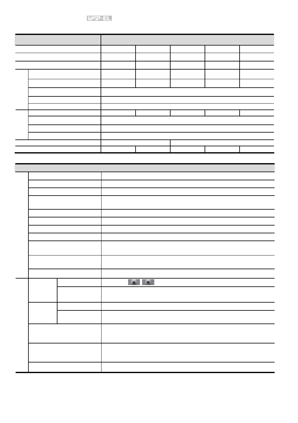
Voltage Class
460V Class
Model Number VFD-XXXEL
004
007
015
022
037
Max. Applicable Motor Output (kW)
0.4
0.75
1.5
2.2
3.7
Max. Applicable Motor Output (hp)
0.5
1.0
2.0
3.0
5.0
Rated Output Capacity (kVA)
1.2
2.0
3.3
4.4
6.8
Rated Output Current (A)
1.5
2.5
4.2
5.5
8.2
Maximum Output Voltage (V)
3-Phase Proportional to Input Voltage
Output Frequency (Hz)
0.1~600 Hz
Outp
ut Rati
ng
Carrier Frequency (kHz)
2-12
Rated Input Current (A)
1.8
3.2
4.3
7.1
9.0
Rated Voltage/Frequency
3-phase, 380-480V, 50/60Hz
Voltage Tolerance
±
10%(342~528V)
Inpu
t Ratin
g
Frequency Tolerance
±
5%(47~63Hz)
Cooling Method
Natural Cooling
Fan Cooling
Weight
(kg)
1.2 1.2 1.2 1.7 1.7
General Specifications
Control System
SPWM(Sinusoidal Pulse Width Modulation) control (V/f control)
Frequency Setting Resolution
0.01Hz
Output Frequency Resolution
0.01Hz
Torque Characteristics
Including the auto-torque/auto-slip compensation; starting torque can be
150% at 5.0Hz
Overload Endurance
150% of rated current for 1 minute
Skip Frequency
Three zones, setting range 0.1-600Hz
Accel/Decel Time
0.1 to 600 seconds (2 Independent settings for Accel/Decel time)
Stall Prevention Level
Setting 20 to 250% of rated current
DC Brake
Operation frequency 0.1-600.0Hz, output 0-100% rated current
Start time 0-60 seconds, stop time 0-60 seconds
Regenerated Brake Torque
Approx. 20% (up to 125% possible with optional brake resistor or externally
mounted brake unit, 1-15hp (0.75-11kW) models have brake chopper built-in)
C
ontr
o
l C
har
acter
isti
cs
V/f Pattern
Adjustable V/f pattern
Keypad
Setting by
Frequency
Setting
External Signal
Potentiometer-5k
Ω/0.5W, 0 to +10VDC, 4 to 20mA, RS-485 interface; Multi-
function Inputs 3 to 6 (15 steps, Jog, up/down)
Keypad
Set by RUN and STOP
Operation
Setting
Signal
External Signal
2 wires/3 wires ((MI1, MI2, MI3)), JOG operation, RS-485 serial interface
(MODBUS), programmable logic controller
Multi-function Input Signal
Multi-step selection 0 to 15, Jog, accel/decel inhibit, 2 accel/decel switches,
counter, external Base Block, ACI/AVI selections, driver reset, UP/DOWN
key settings, NPN/PNP input selection
Multi-function Output Indication
AC drive operating, frequency attained, zero speed, Base Block, fault
indication, overheat alarm, emergency stop and status selections of input
terminals
Oper
ati
ng C
har
acter
ist
ics
Analog Output Signal
Output frequency/current