4 control terminals, 4 control terminals -12 – Delta Electronics AC Motor Drive VFD-EL User Manual
Page 33
Chapter 2 Installation and Wiring|
2-12
Revision August 2008, 2ELE, V1.02
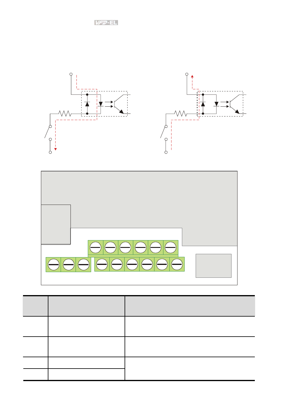
2.4 Control Terminals
Circuit diagram for digital inputs (NPN current 16mA.)
+24V
DCM
NPN Mode
1
3
4
2
2
1
+24V
DCM
PNP Mode
1
3
4
2
2
1
The position of the control terminals
RS-485
10V
MI1 MI3 MI5
24V
AVI
RA RB RC
MI2 MI4 MI6 DCM
ACM
AFM
Terminal symbols and functions
Terminal
Symbol
Terminal Function
Factory Settings (NPN mode)
ON: Connect to DCM
MI1 Forward-Stop
command
ON:
Run in MI1 direction
OFF:
Stop acc. to Stop Method
MI2 Reverse-Stop
command
ON:
Run in MI2 direction
OFF:
Stop acc. to Stop Method
MI3 Multi-function
Input
3
MI4 Multi-function
Input
4
Refer to Pr.04.05 to Pr.04.08 for programming the
Multi-function Inputs.
See also other documents in the category Delta Electronics Tools:
- AC Motor Drive VFD-G (183 pages)
- SMT Power Inductor SIL104R (1 page)
- Q48SB (2 pages)
- Planar DC/DC Transformer ER/ER(Plate) 22 (1 page)
- SMT Power Inductor HCB1190B (1 page)
- Series E48SR (15 pages)
- E48SR12007 (15 pages)
- SMT Power Inductor SIWC1360 (1 page)
- PFC Chokes PFC2815V Series (1 page)
- SMT Power Inductor SIB86 (1 page)
- PMC-24V050W1AA (2 pages)
- SMT Power Inductor HCB1050 (1 page)
- SMT Power Inductor HAH1330 (1 page)
- PFC Chokes PFC4120V Series (1 page)
- PFC Choke PFC3520V Series (1 page)
- SMT Power Inductor HCB1047B (1 page)
- SMT Power Inductor HAH1365 (1 page)
- SMT Power Inductor HMS1355 (1 page)
- Series S48SA (13 pages)
- E48SC (2 pages)
- SMT Power Inductor SILM106 (1 page)
- Delphi Series L48DB (2 pages)
- S48SA (13 pages)
- E36SR (2 pages)
- 3KVA (31 pages)
- SMT Power Inductor HMU1056L (1 page)
- Through Hole Power Inductors THCBR1090 (1 page)
- SMT Power Inductor SIL625 (1 page)
- SMT Power Inductor 1378(S) (1 page)
- Through Hole Power Inductors 1411 (1 page)
- Current Sense Transformers TCE1310H (1 page)
- H48SR (13 pages)
- Series E48SH (15 pages)
- Through Hole Power Inductors THAH1095 (1 page)
- Suppression Inductors LFU09V (1 page)
- SMT Power Inductor HCB0740A (1 page)
- Power Output Module DVPPS01 (2 pages)
- SMT Power Inductor SIR74 (1 page)
- L36SA (2 pages)
- 4.5V~ 5.5V (3 pages)
- Delphi Series V48SB (2 pages)
- Series S48SP (14 pages)
- Series 240W (11 pages)
- Delphi Series E24SR (15 pages)