Adjust carriage bearings, Miiqnrngni anci mujuslitieni – Sears 113.197611 User Manual
Page 44
Attention! The text in this document has been recognized automatically. To view the original document, you can use the "Original mode".
I S
Jb
.^ml
^¡i^l ■ ■ W Jb ^N
b
MIIQnrnGni anCi MujUSliTieni
11
^
s
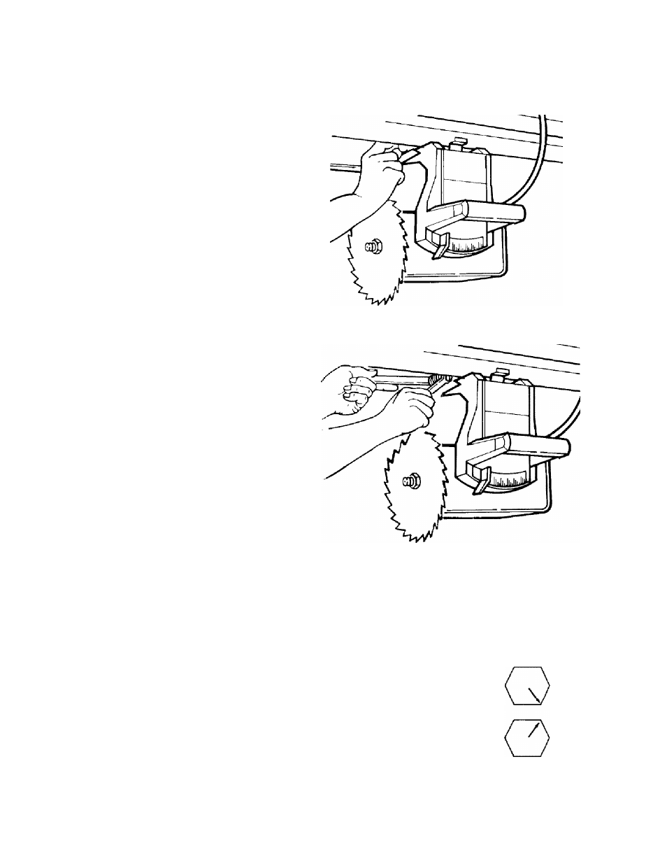
Adjust Carriage Bearings
The goal of this adjustment is to eliminate
looseness between the carriage bearings
and the radial arm. The blade carriage
should roll freely along the entire length
of the radial arm, but with some resistance.
1. With blade still locked in out-rip posi
tion, unlock rip lock and move blade car
riage to rear as far as it will go.
2. From front of saw, look up under
radial arm to identify front carriage bear
ing. With thumb and index finger, get
pinch-hold inside groove of bearing.
Apply force to bearing and at same time,
pull blade carriage forward. Force should
not
stop bearing from turning while car
riage is moving.
3. If you can stop bearing from turning
while carriage is moving, adjust bearings:
i) position blade carriage for good access
to front and rear bearings
ii) lock rip lock
hi) hold front bearing bolt in place and
loosen nut
iv) rotate bolt a few degrees, then tighten
nut.
Note:
Carriage bearings have eccentric
bolts. High side of each bolt is marked by
an arrow. Adjust rear carriage bearing
same amount, but in opposite direction, as
you adjust front carriage bearing.
Note:
Do not overtighten. Overtightening
can cause blade carriage to move with dif
ficulty and will reduce life of track and
bearings.
4. Before proceeding to next section,
repeat steps to Square Blade to Table for
Ripping, because adjusting carriage bear
ings affects that alignment.
\
\
OK
____ / Both Arrows Point Up
/
\
OK
/ j
Both Arrows Point Down
'
\ WRONG
/
)
One Arrow Points Up
■vl----/ One Arrow Points Down
44