Cisco 3200 User Manual
Page 70
6-2
Cisco TelePresence System 3200
OL-14521-01
Chapter 6 Building the First Row Table Assembly
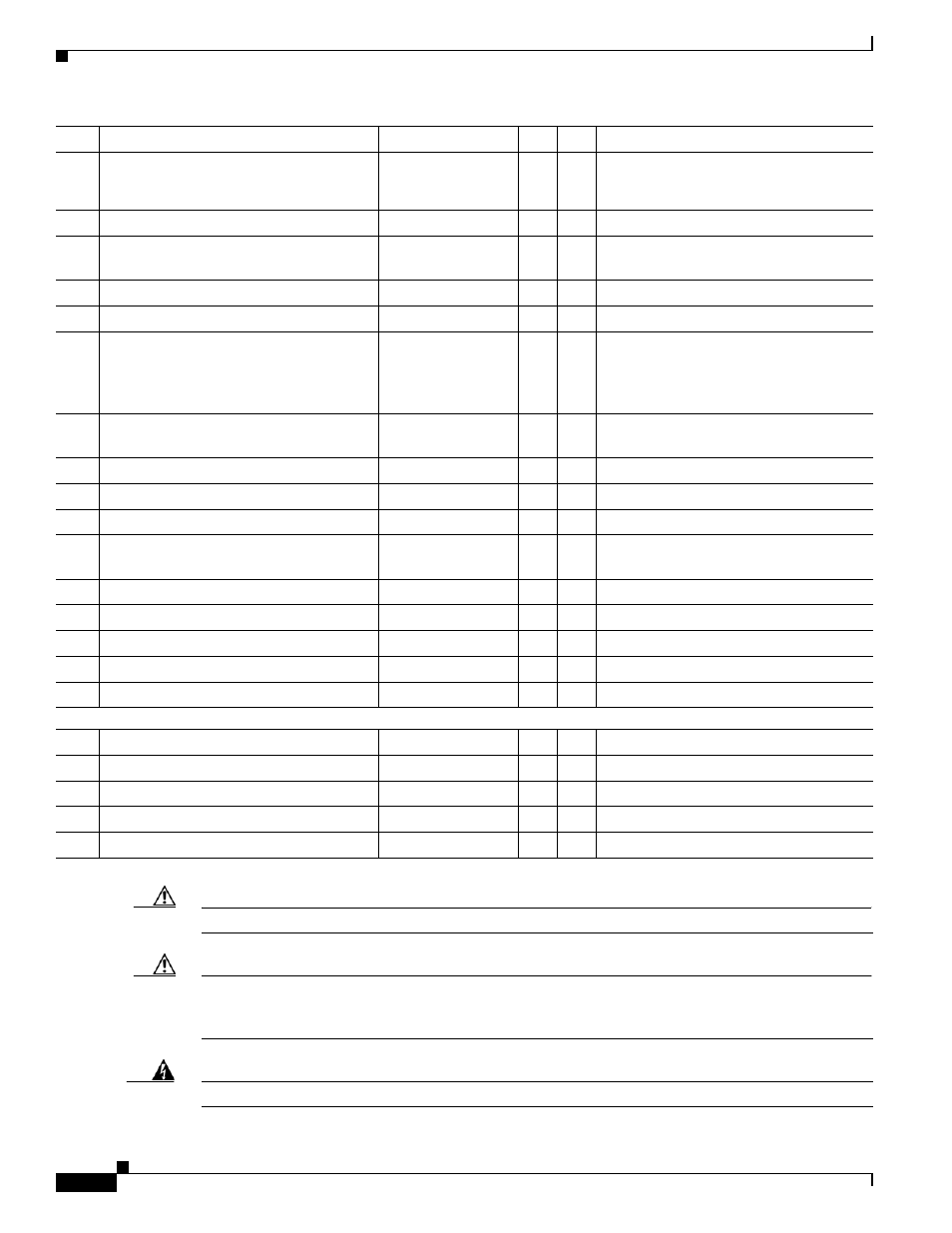
Parts List
Caution
The table segments are unstable during assembly. Use caution, and support all structures as required.
Caution
Some system components have metal and plastic edges with hard angles. These edges are exposed until
you complete system assembly. Use caution when you move around the system during assembly to avoid
contact with any exposed system edges.
Warning
Only trained and qualified personnel should be allowed to install, replace, or service this equipment.
14
and
15
M8 x 20 mm screws, black
48-2273-01
30
1
16
Phillips head wood screws
8
1
Included with Left tabletop hinge.
17
Plate for left side table
1
Installs on the side closest to the table
door.
18
I/O blank: large
700-23806-xx
1
19
I/O blank: small
700-23807-xx
6
1
20
I/O modules: power/Ethernet
74-xxxx-xx
6
1
Part number changes per country. Refer
to
for part
number.
21
I/O Module Cover plate
700-23305-xx
50-
54
22
10 m Cat6 Ethernet cable
37-0901-xx
6
1
23
3 m Jumper cord
37-0833-xx
9
1
24
M4 nuts
49-0326
20
1
25
M4 x 12 mm screws, black
48-2426-xx
Kit # 69-1878-xx
10
1
26
Microphone
74-4743-xx
3
1
27
M4 x 30 mm screws
1
Included in Microphone kit.
28
M4 washers
1
Included in Microphone kit.
29
Table hinge safety hinge
To be provided
1
30
M8 x 20 mm screws
48-2273-01
1
Privacy Panel Assembly
1
Privacy panel: Center left
700-23333-xx
1
34
2
Privacy panel: center
700-23334-xx
1
34
3
Privacy panel: Center right
700-23332-xx
1
34
4
Privacy panel: right wing
700-23362-xx
1
14
5
M8 x 20 mm screws
48-2273-xx
1
Key
Part Description
Part Number
Qty
Ctn
Notes