Cisco 3200 User Manual
Page 44
5-2
Cisco TelePresence System 3200
OL-14521-01
Chapter 5 Building the Lighting Assembly
Parts List
Warning
Only trained and qualified personnel should be allowed to install, replace, or service this equipment.
Caution
Metal and plastic edges can be sharp. Cisco recommends you wear safety gloves and safety glasses when
attaching the lighting assembly.
Caution
Some system components have metal and plastic edges with hard angles. These edges are exposed until
you complete system assembly. Use caution when you move around the system during assembly to avoid
contact with any exposed system edges.
Note
The directions left and right refer to the assembly as you face the Plasma displays.
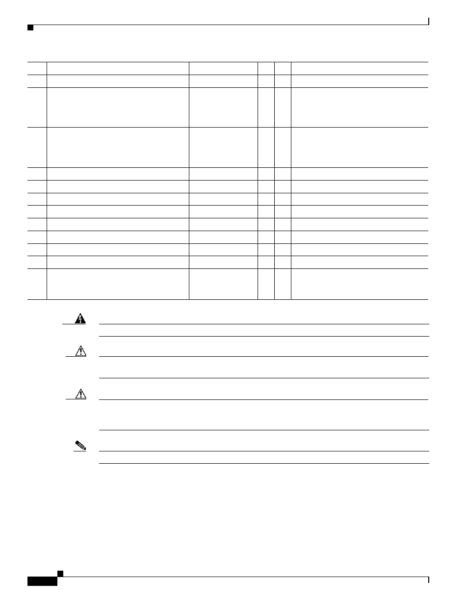
23
Light “cup” bracket
700-23737-xx
2
43
24
5-foot center light fixture
74-5361-xx
CTS-LT-FX-
5FT-GN
Kit #95-8932-xx
3
31
See
for
Europe- and Japan-specific lighting
fixtures.
25
4-foot side light fixture
74-5362-xx
CTS-LT-FX-
5FT-GN
Kit #95-8932-xx
2
30,
31
See
for
Europe- and Japan-specific lighting
fixtures.
26
M8 x 70 mm screws
48-2274-xx
10
1
27
M8 x 16 mm pan head screw, white
48-2432-xx
1
28
M8 x 20 mm flat head screw, white
48-2433-xx
10
49
29
Diffuser Panel braces / H-clips
700-25050-xx
2
49
30
Compliance sticker for plasma display
47-21525-xx
1
1
31
M8 x 16 mm pan head screw, black
48-2430-xx
2
1
32
Reflector bottom tray: right side top
700-27762-xx
1
49
33
Reflector bottom: right end
700-27763-xx
1
49
Touch-up paint, white
74-5247-xx
1
1
Use this paint on the light reflectors to fix
any minor cosmetic issues caused by
shipping and handling.
Key
Part Description
Part Number
Qty Ctn Notes