Step 4 – Cisco 3200 User Manual
Page 160
9-6
Cisco TelePresence System 3200
OL-14521-01
Chapter 9 Routing Power and Signal Cables
Power Requirements for the Cisco TelePresence 3200
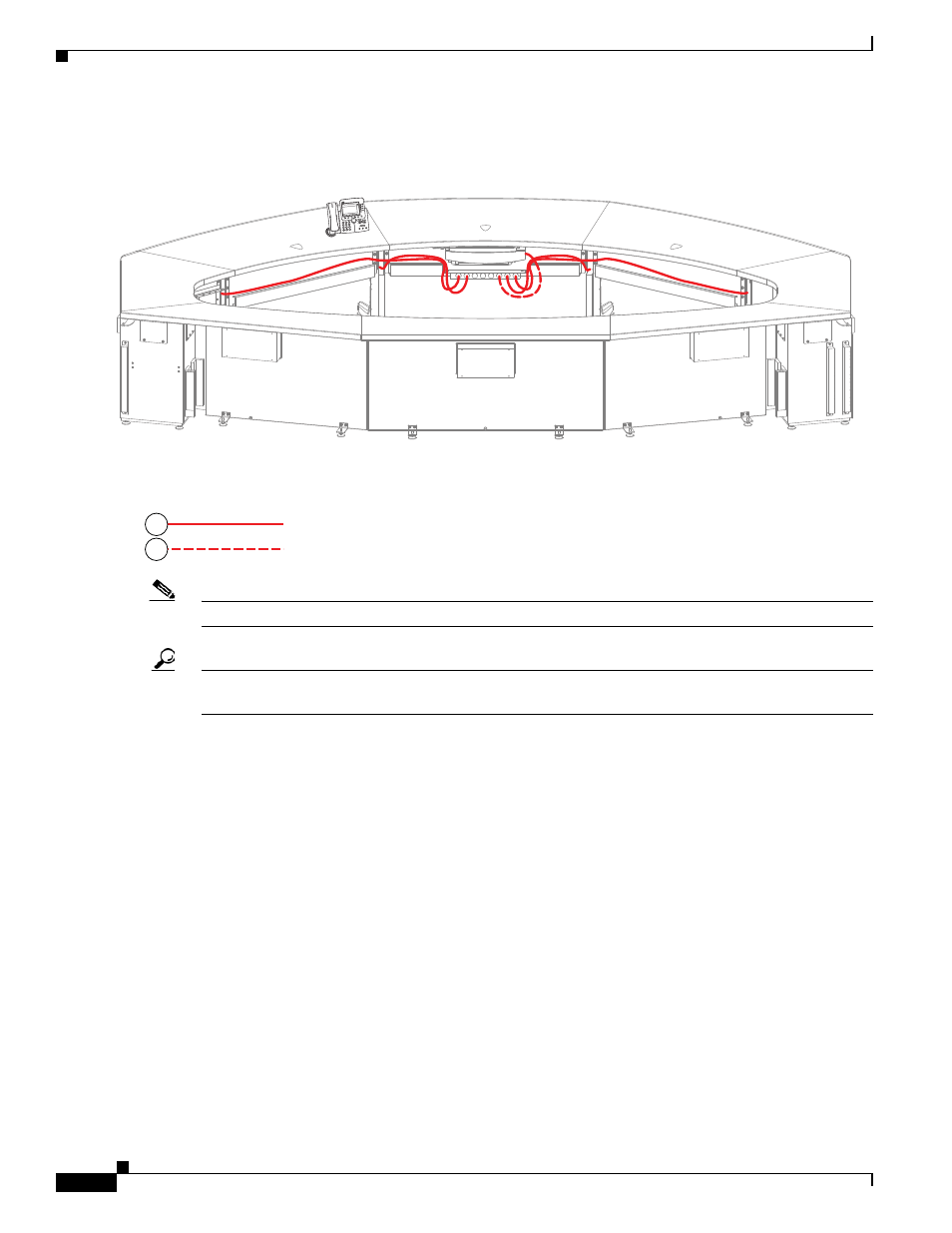
Step 4
Route the power cables for the first row table assembly.
Figure 9-4
First Row Table Assembly Cable Routing
Note
The six jumper cords from the I/O modules in the table legs route to the center PDU.
Tip
Before plugging the Table leg jumper cords into the Table PDU, label each one. For example, Outer Left
Power, Inner Right Power.
201204
TelePresen
ce
3
DEF
6
MNO
9
WXYZ
#
2
ABC
5
JKL
8
TUV
0
OPER
1
4
GHI
7
PQRS
CISCO IP PHO
NE
7970
Table Leg Power
Projector Power
8
9