Step 3 – Cisco 3200 User Manual
Page 142
8-6
Cisco TelePresence System 3200
OL-14521-01
Chapter 8 Assembling the Remaining Cisco TelePresence Elements
Parts List
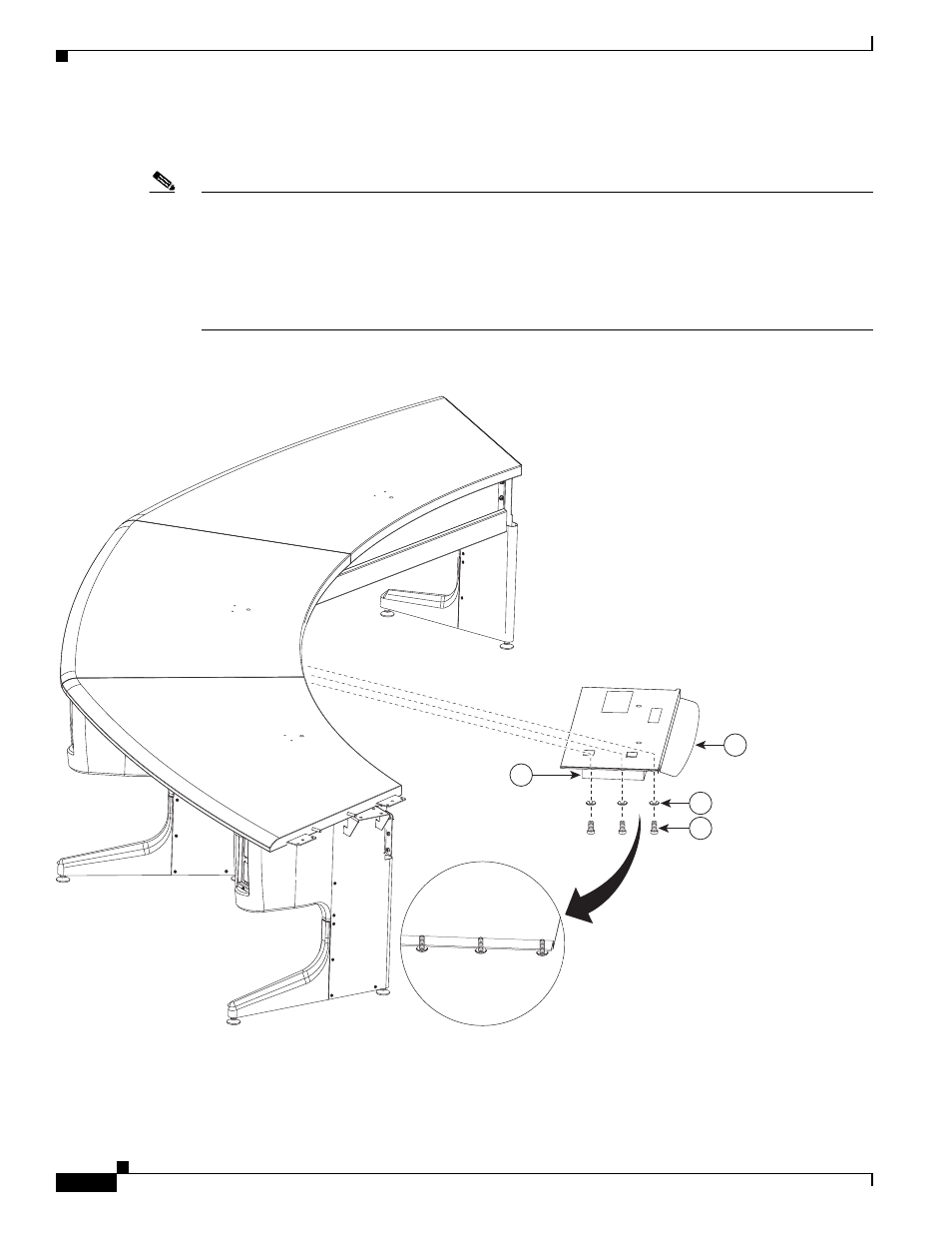
Step 3
Attach the projector to the projector mounting bracket, and attach the assembly to the underside of the
center Table segment.
Note
•
The bracket slides between two rows of screws. Screw the six screws with washers into the underside
of the center table segment and slide the bracket between the two rows of screws; then, tighten the
screws.
•
There is a channel that is cut into the underside of the table. Route the cable for the center
microphone into this channel, using tape if required, so that the microphone cable is not pinched
between the bracket and the table.
Figure 8-3
Projector Assembly
201169
2
1
6
4