Fiber interface bridge installation (fib-1000) – Potter PFC-6075R User Manual
Page 44
3-38
PFC-6075R • 5403594 • REV D • 9/14
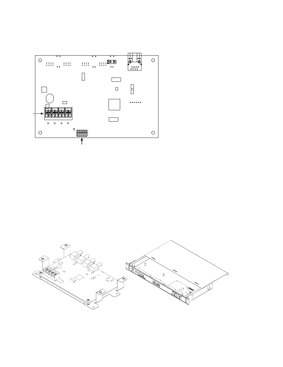
Setting Addresses
The FCB-1000's address is set by dip switch S1. The address must be set in the range of one (1) to thirty-one (1–31) to be
recognized by the panel. (Refer to the "P-Link Addresses" table shown earlier in this section for DIP switch programming.)
Figure 48. FCB-1000 Back Panel View Showing Dip Switch Location
Fiber Interface Bridge Installation (FIB-1000)
The panel supports up to thirty (30) FIB-1000s (Fiber Interface Bridge), which enables the 4-wire P-Link bus to be converted to
and/or from the fiber optic cable.
• Utilizes multimode 62.5/125 micron fiber optic cable
• Cable Length up to 2000 meters or 6500 feet
• Installed in pairs (refer to the "FIB-1000 Wiring" heading for details)
The first installed FIB-1000 can be mounted into any of the compatible fire enclosures, in either of the AE-8 or AE-14, or the
optional rack-mount kit (FIB-1000RM). The FIB-1000RM includes a standard 19 inch rack-mount enclosure, which can then be
installed directly in an equipment rack. The second installed FIB-1000 must be installed in a PSN-1000E cabinet as illustrated in
the following drawings.
Figure 49. FIB-1000 Bridge & FIB-1000RM Rack Mount
DWG #608-11
DWG #608-12
Dip Switch
DWG #608-20
P-Link
Connections
S1