I/o 1 i/o 2 – Potter PFC-6075R User Manual
Page 34
3-28
PFC-6075R • 5403594 • REV D • 9/14
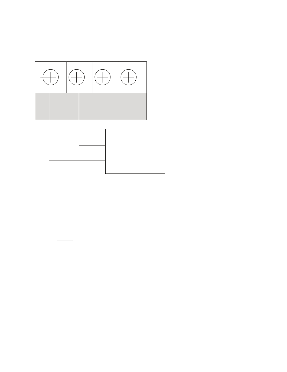
Reverse Polarity Communication Line Circuit
Only I/O 1 and I/O 2 on the PFC-6075R can be programmed as reverse polarity circuits. The short circuit current is rated at
24 VDC and 14 mA maximum. Please refer to the figure below for an example of wiring a reverse polarity communication line
circuit.
Figure 28. Reverse Polarity Communication Line Circuit Wiring
Notes:
1. The panel has ground fault detection on reverse polarity circuits; impedance to ground for ground fault detection
is 0 ohms.
2. The short circuit current is power limited and supervised by a Keltron TTM-RPS transmitter module.
3. When configured for reverse polarity, the PFC-6075R will indicate alarm and trouble events to a remote site.
4. The Alarms override trouble conditions.
DWG #602-8A
Panel
Connection
I/O 1 I/O 2
-
+ -
+
Keltron
TTM-RPS
+
-
Note: IO circuit must configured as a Reverse Polarity circuit.
This connection is limited to same room installation . This connection shall be
limited to 20 feet and enclosed in conduit or equivalently protected against
mechanical injury .