Municipal box connection, Relay outputs – Potter PFC-6075R User Manual
Page 118
6-112
PFC-6075R • 5403594 • REV D • 9/14
Municipal Box Connection
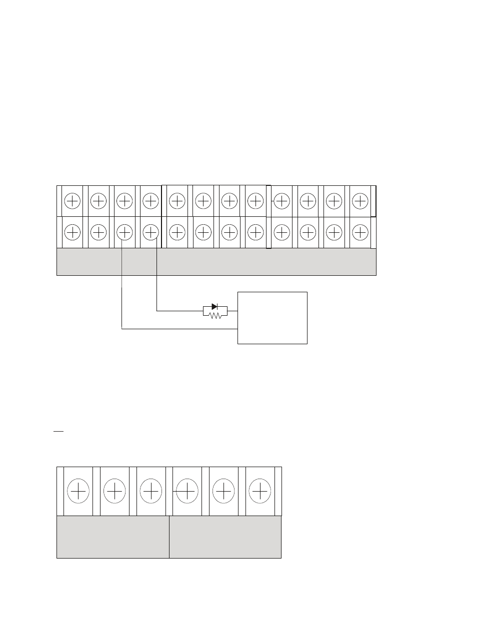
When the PSN-1000/PSN-1000(E) is programmed as a municipal box connection, the circuit is power limited and supervised for
open and short circuit conditions. It also provides a local energy connection. Please refer to the figure shown below for a wiring
example.
Configuration Characteristics
y
y
NAC1-NAC6's trip current is 3 amps.
y
y
Maximum voltage rating is 24 VDC.
Notes:
1. The panel has ground fault detection on municipal box connection circuits.
2. The impedance to ground for ground fault detection is 0 ohms.
Figure 156. PSN-1000 Configured as Municipal Box
-
I1 + - NAC 1 + - NAC 5 + - NAC 3 +
-
+ A B
-
I2 + - NAC 2 + - NAC 4 + - NAC 6 +
-
+ A B
P-LINK
Notes:
The EOL device shall be installed in the same electrical
enclosure as the Municipal Box.
Municipal
Box
+
-
End of line device
5.1k ohm 1/2W
Part #3005012
Relay Outputs
The board has two (2) relay outputs: a dedicated Trouble relay and a Low AC relay. The dedicated Trouble relay is a failsafe
trouble relay that changes position anytime a trouble condition occurs.
The relays have a contact rating is 24VDC / 3.0A, 125VAC / 3A, and a Power Factor of 1.0. These outputs are non-power limited
and are not supervised.
Note: If the power supply is power-limited, then the outputs are power limited.
Figure 157. PSN-1000's Relay Outputs
LOW AC
NC COM NO
TROUBLE
NC COM NO
DWG #602-31
DWG #602-32