Fire communications bridge installation (fcb-1000) – Potter PFC-6075R User Manual
Page 43
3-37
PFC-6075R • 5403594 • REV D • 9/14
Setting Addresses
The RLY-5's address is set by dip switch S1, which is located on the back of the board. The address must be set in the range of
one to thirty-one (1–31) to be recognized by the panel. (Refer to the "P-Link Addresses" table shown earlier in this section for
DIP switch programming.)
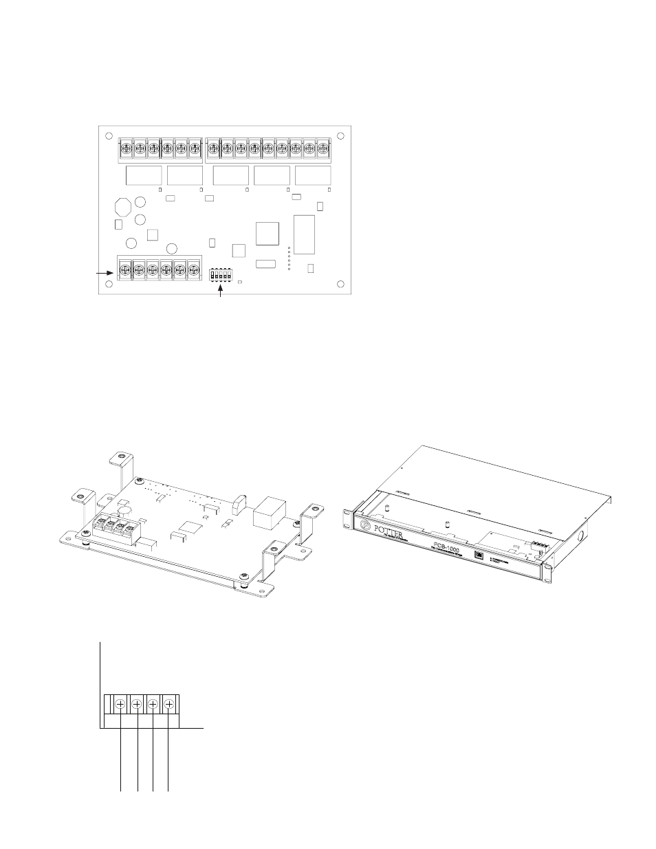
Figure 45. Relay Board Back Panel View Showing Dip Switch Location
Fire Communications Bridge Installation (FCB-1000)
This panel supports one (1) Fire Communications Bridge accessory. This module provides an optional remote IP connection for
IP reporting functionality. The FCB-1000 is controlled over the 4-wire P-Link connection. This then can be mounted inside the
AE-8 or AE-14 accessory cabinets, or the optional rack-mount kit (FCB-1000RM). The FCB-1000RM includes a standard 19
inch rack-mount enclosure, which can then be installed directly into the IT equipment rack.
Note: The Ethernet IP connection is limited to same room installation. This connection shall be limited to 20 feet and enclosed in
conduit or equivalently protected against mechanical injury.
Figure 46. FCB-1000 Board & FCB-1000RM Showing Rack Mount
Figure 47. FCB-1000 Wiring to Control Panel Example
DWG #608-13
DWG #608-14
DWG #608-21
Dip Switches
P-Link
Connections
S1
DWG #608-26
P-Link
-
+ A B
P-Link from
control panel
Example:
Powered by
control panel