Analog sounder base (asb) – Potter PFC-6075R User Manual
Page 26
3-20
PFC-6075R • 5403594 • REV D • 9/14
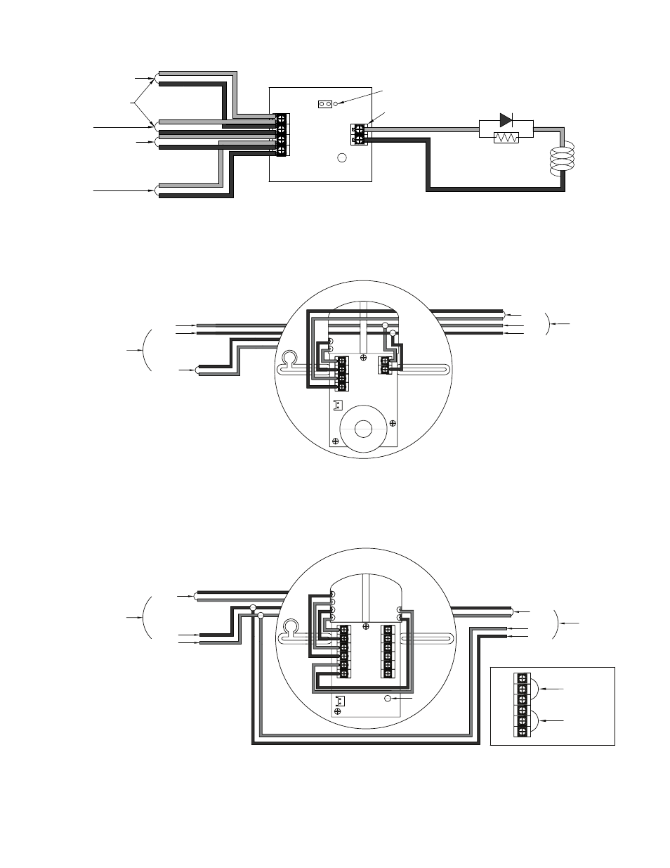
Figure 19. Example of MOM-4 Wiring as a Releasing Device
Analog Sounder Base (ASB)
Figure 20. Example of Analog Sounder Base Wiring
Notes:
1. The supply power must be coded in order for the output to be coded.
2. ASB does not generate a coded output. It will track the pattern delivered to its 24 VDC input.
Analog Relay Base (ARB)
Figure 21. Example
of
Analog
Relay
Base
Wiring
Monitored Output Module
Model No. MOM-4
From FACP or Previous Module
To Next Module
From FACP or Previous Module
To Next Module
24-
24+
S-
S+
A-
A+
SLC Loop
LED
JP1
Select DC
Output Rating:
24VDC / 2.0A
Releasing
Device
End of Line Device
5.1Kohm 1/2W
Part#3005012
Note:
EOL Device shall be installed in the same
electrical enclosure as the releasing device
DWG #602-35
Analog Sounder Base
Model No. ASB
S-
S+
S+
S-
TB1
24+
24-
S-
S+
SLC Loop
24 VDC-
24 VDC+
From FACP or
Previous Module
SLC Loop
24 VDC+
24 VDC-
To Next Module
DWG #593-19
To Next Module
Analog Relay Base
Model No. ARB
S-
24+
S+
24-
S+
S-
NO2
NO1
NC1
C1(8A)
C2(2A)
NC2
TB1
TB2
SLC Loop
24 VDC+
24 VDC-
From FACP or
Previous Module
SLC Loop
24 VDC+
24 VDC-
LED
NO2
NO1
NC1
C1(8A)
C2(2A)
NC2
TB2
8.0A / 240VAC
8.0A / 30VDC
2.0A / 240VAC
2.0A / 30VDC
DWG #593-20