Repeater output – Potter PFC-6075R User Manual
Page 117
6-111
PFC-6075R • 5403594 • REV D • 9/14
Repeater Output
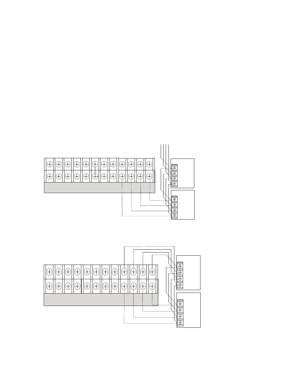
The PSN-1000/PSN-1000(E) repeater output provides power which supports additional P-Link devices, including LCD Annunciators
and/or SLC Loop expanders. This is possible because the P-Link repeater output reconditions and repeats all P-Link communications.
Refer to the following figures for examples of Class A and B wiring.
Configuration Characteristics
y
y
PSN-1000 current rating is one (1) amp.
y
y
PSN-1000 voltage rating is 24 VDC.
y
y
The maximum wire length is 6,500 feet.
y
y
Wiring is fully supervised and power limited.
Maximum Wire Resistance Formula
The maximum resistance is based on the load placed on the circuit. To calculate the maximum wire resistance, use the following
formula:
(Total Annunciator Alarm Current) x (Wire Resistance) < 6 Volts
Note: Any connection to ground of 0 ohms will be annunciated as a ground fault.
Figure 154. P-Link Class B (Repeater) Wiring Example
Figure 155. P-Link Class A Wiring Example
DWG #602-28
-
I1 + - NAC 1 + - NAC 5 + - NAC 3 +
-
+ A B
-
I2 + - NAC 2 + - NAC 4 + - NAC 6 +
-
+ A B
P-LINK
To the next device
-
+
A
B
Expansion
Device
-
+
A
B
Expansion
Device
- I1 + - NAC 1 + - NAC 5 + - NAC 3 +
-
+ A B
- I2 + - NAC 2 + - NAC 4 + - NAC 6 +
-
+ A B
P-LINK
-
+
A
B
Expansion
Device
-
+
A
B
Expansion
Device
DWG #602-29