Potter PFC-6075R User Manual
Page 108
6-102
PFC-6075R • 5403594 • REV D • 9/14
Section 6: PSN-1000 / PSN-1000(E) – Installing, Operating & Programming
The PSN-1000 and PSN-1000(E) power supply boards provide power and communication expansion capability to the
PFC-6000 series control panels. They provide an electrically isolated P-Link repeater output that supports additional power
and communications distance. The PSN-1000(E)'s larger cabinet allows space for mounting up to six (6) additional P-Link and
expansion cards (i.e., FIB-1000, etc.).
Board Specifications
Cabinet Descriptions
y
y
Sixteen (16) gauge sheet steel with hinged, locked doors
y
y
Enclosure dimensions
PSN-1000 – 16" x 17" x 3-7/8" (non-removable door)
PSN-1000(E) – 26" x 17.6" x 3.75" (removable door)
Visual Indicators
y
y
LED indicators (Green & Amber)
Environmental Specifications
y
y
Mount indoors only.
y
y
Temperature 32° to 120°F, humidity 93% non-condensing.
y
y
Verify panel is properly grounded.
y
y
Remove all electronic assemblies prior to any drilling, filing, reaming, or punching of the enclosure. When possible, make
all cable entries from the sides, bottom, or rear of the cabinet. Verify that they will not interfere with the batteries or other
components.
y
y
The panel must be tested and maintained in accordance with all local and national codes and ordinances. Refer to
Appendix D: PSN-1000/PSN-1000(E) Maintenance and Testing for information on maintenance and testing
recommendations.
Electrical Specifications
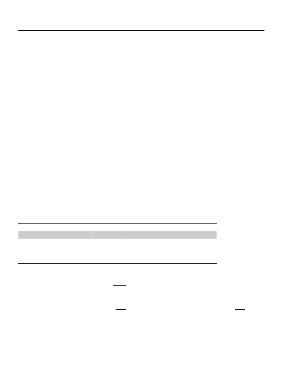
Please refer to the table below for the board's electrical specifications:
Table 22: PSN-1000/PSN-1000(E) Board Electrical Specifications
# NACs
Rating per NAC
Input Circuits
Style and Class
6
3 Amp
1 Amp
Class A or B
NACs are Power Limited
Note: Refer to the "NACs Wiring" topic located in
this section for Class A wiring requirements.
Wiring Specifications
There are several wiring requirements to consider before connecting circuits to the PSN-1000/PSN-1000(E) board:
1) the circuit separation, and 2) the wiring types.
Circuit Separation
y
y
Separations between the different wiring types must be maintained by at least ¼ inch and the wire insulation must be for the
higher voltage.
y
y
The two cabinets have various conduit knockouts located for ease of wire installation and allowing the installer to maintain
power limited and non-power limited connections.