Potter PFC-6075R User Manual
Page 25
3-19
PFC-6075R • 5403594 • REV D • 9/14
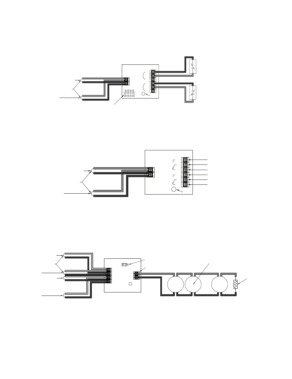
When configuring a Class B, the DCM-4 has two (2) addresses. If address No.1 is set, input circuit No.1 (NO1, C1) will be
addressed as No.1, and input circuit No.2 (NO2, C2) will automatically be addressed as No.2. Refer to the figure below for an
example of wiring a Class B DCM-4.
Figure 16. DCM-4 with Two Class B Circuits
S-
S+
SLC Loop
To Next Module
From FACP or Previous Module
Dual Contact Module
Model No. DCM-4
LED
Note: The resistance of external wiring shall be less that 100Ω.
The capacitance of external wiring shall be less than 1 micro farads.
JP1
Select Style 4
NO1
C1
Z1
NO2
C2
Z2
Address #
Address #+1
DWG #593-16
Twin Relay Module – 4 inch mount (TRM-4)
The TRM-4 has two (2) contacts that are active simultaneously when TRM-4 is in the active mode. Normal output is nonpower-
limited, unless the power supply connected to the TRM-4 is power-limited and the circuits are power-limited.
Figure 17. Example of TRM-4 Wiring
S-
S+
SLC Loop
To Next Module
From FACP or Previous Module
Twin Relay Module
Model No. TRM-4
LED
NO1
C1
NC1
NO2
C2
NC2
Contact Rating:
24VDC / 2.0A
125VAC / .5A
Normally Open 1
Common 1
Normally Closed 1
Normally Open 2
Common 2
Normally Closed 2
DWG. #593-17
Monitored Output Module – 4 inch mount (MOM-4)
If the power supply connected to the MOM-4 is power limited, then the outputs are power limited. The MOM-4 module may be
wired as a releasing device. Examples of a MOM-4 wired as a conventional and a releasing application are provided here.
Figure 18. Example of MOM-4 with NAC Connections
Monitored Output Module
Model No. MOM-4
From FACP or Previous Module
To Next Module
From FACP or Previous Module
To Next Module
24-
24+
S-
S+
A-
A+
SLC Loop
LED
JP1
Select DC
Notification Appliance
5.1KΩ 1/2W EOLR
_
+
_
+
_
+
Output Rating:
24VDC / 2.0A
DWG #593-18