53 digital i/o connections, Toshiba – Toshiba LF494 User Manual
Page 28
Attention! The text in this document has been recognized automatically. To view the original document, you can use the "Original mode".
TOSHIBA
6 F 8 A 0 7 7 4
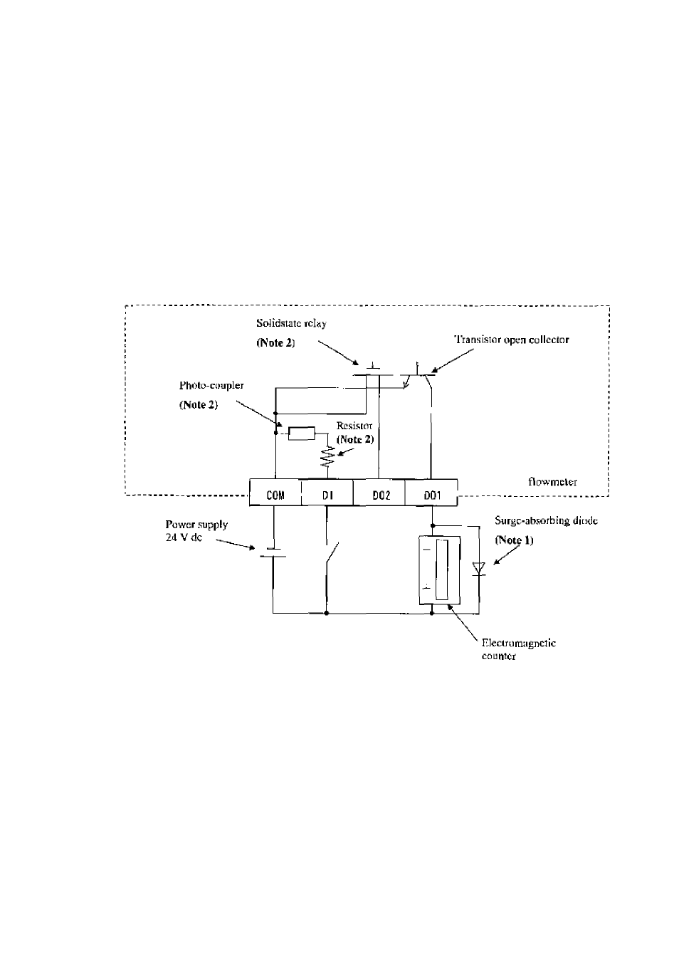
53 Digital I/O Connections
Digital I/O icrmmEils cottsiM ol conlact oulpul lerniiiials (jilatidard DOl
Eind
optional
D02), voJlage signal input terminal (Dl, opcioiial), and signal common terminal {COM).
Hach terminal (DOl, D02 and DI) is isolated from internal circuits. Terminal (COM) is
the signal common for the other three terminals {DOl, DOl and DI).
Functions can be assigned for each xnninal with Ihe LCD control keys (option). See
Chapter 10, ‘‘Digital I/O Functions/
To connect an electromagnetic relay ot counter lo the contact output tcrrtiinal (DOl or 1>02)^
put a surge-absorbing diode into the input circuil of the relay or counter. See Figure 5.3 for
an example of electromagnetic counter connection,
Note I: Use a surge-absorbing diode of the rating: current rating lAand voltage rating
200 V minimum.
Note 2: The Solidstaie relay, photo-coupler and resistor are not provided for the standard
model (the one whth no digital I/O specifications). l.eavc the terminals for D
0 2
and
Dl open.
Figure 5.3 Electromagnetic Counter Connection Exntnple
-
2 7 -