4,2,2 installation procedure, Toshiba – Toshiba LF494 User Manual
Page 18
Attention! The text in this document has been recognized automatically. To view the original document, you can use the "Original mode".
TOSHIBA
6 F 8 A 0 7 7 4
4,2,2
Installation Procedure
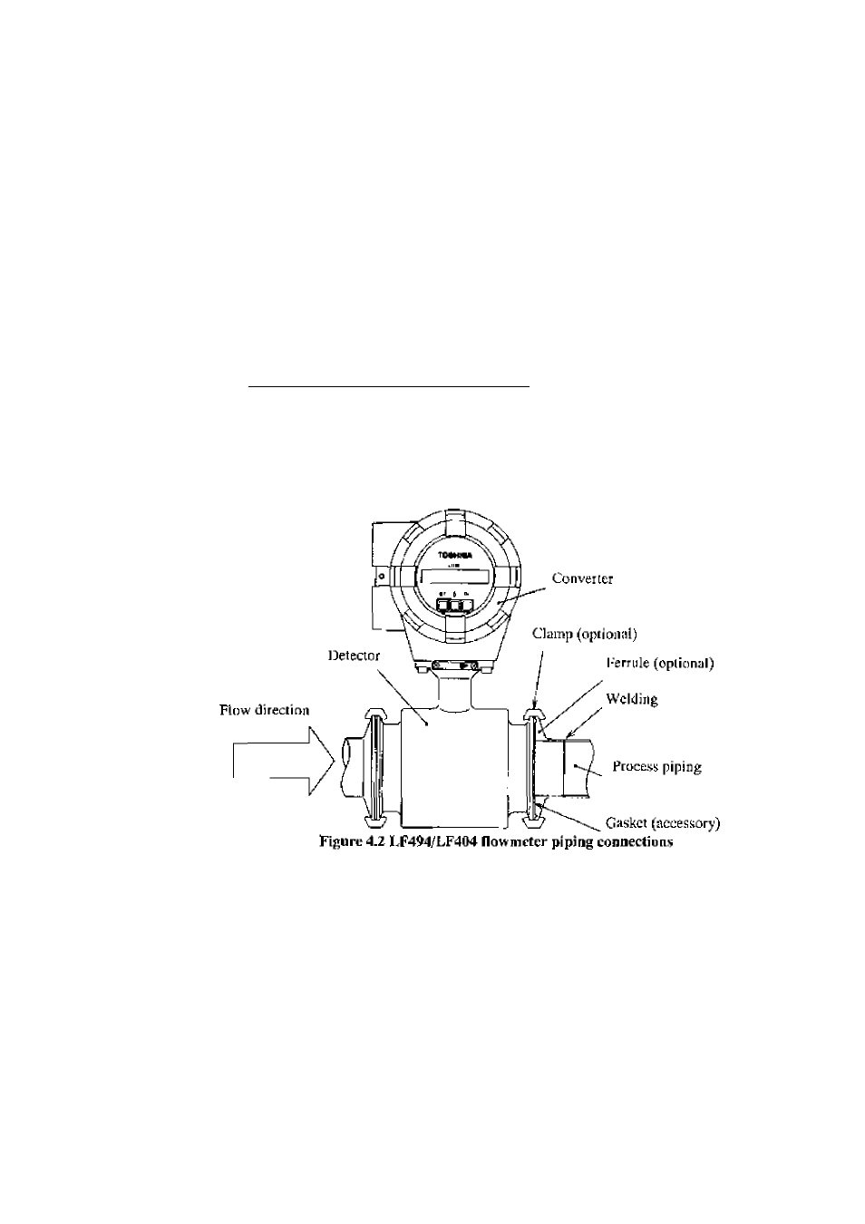
The LF4y4/LF404 adopis the ISO ^^^52 ditmp connection mcihcnJ-
To mount the 1.F494/LF404, see Figure 4.2 and follow the procedure below;
1. Weld a ferrule of the detector to the proces.s pipe on both upstream and downstream
sides.
2 .
Install the LJ’494/LI-404 between the two tcrrulcs w'hicli were welded to the pnjcess
pipes above.
3 .
InstaU a gasket betw^een ;he grooves of theferruJeon the detector side and lhal of the
ferrule on the process pipe for both upstream and dow^nslream sides,
1
iicn place a
clamp over the joined ferrules as shown in I’igure 4,2 and tigliien with the screw' for
both upstream and downstream process pipes._______________________________
IMPORTANT
When high-temperature fluid is being nieasuredj radiant heal from ihe detector pipe surface and
adjoining pipes may cause the ambient temperature of the converter to go above 60
° C .
If the
ambient tempera lure goes above 60^ C, (ry to lower the temperature by measures such as wrap
ping hcal-insulating materials over the detector pipe and adjoining pipes.
-
1 7
-