Digital i/o functions, Toshiba – Toshiba LF494 User Manual
Page 107
Attention! The text in this document has been recognized automatically. To view the original document, you can use the "Original mode".
TOSHIBA
6 F 8 A 0 7 7.4,
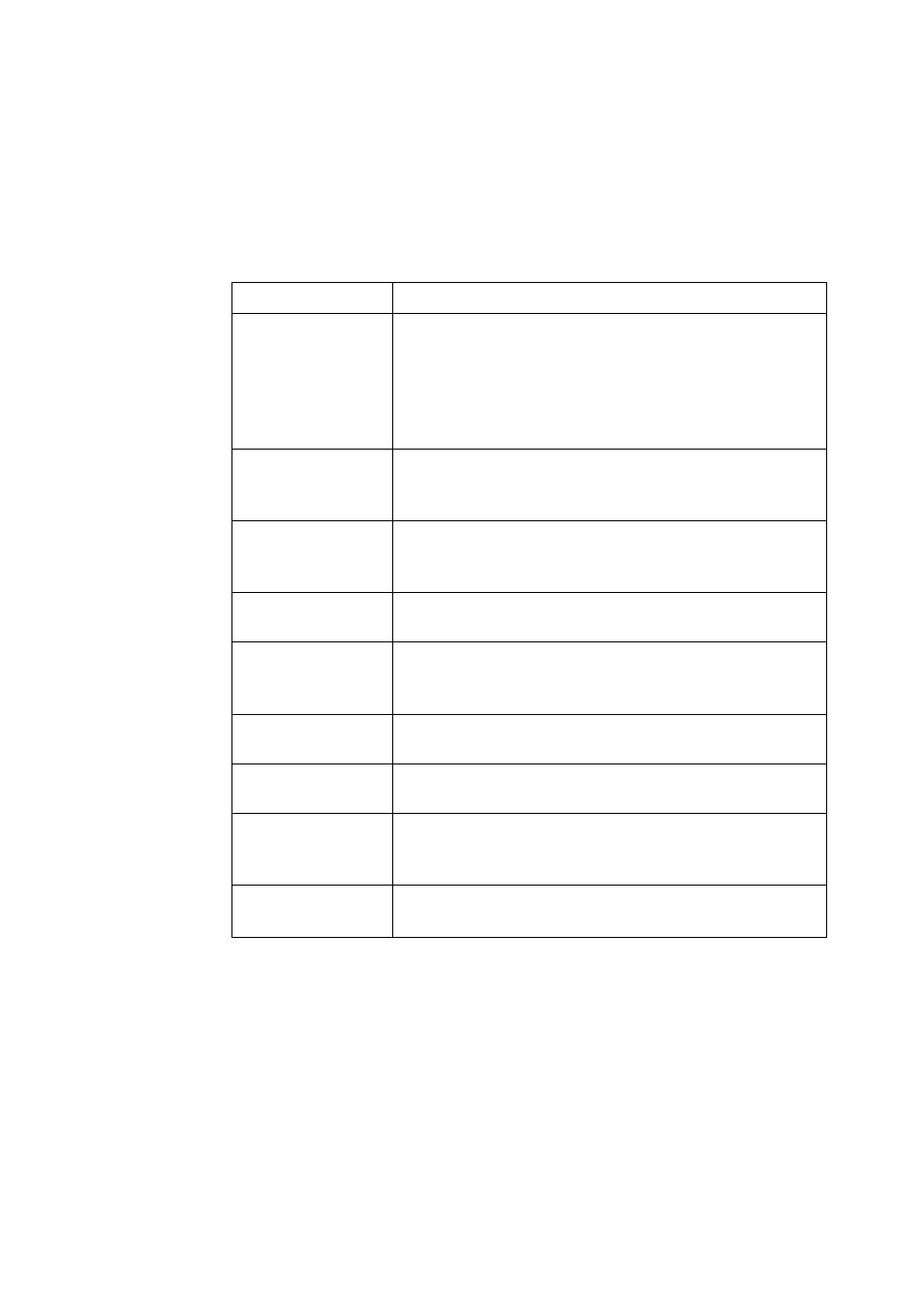
10. Digital I/O Functions
The LI 404 converter hits one standard digital output (^>01) terminal, This terminal can be
used in various ways, such us a pulse output, or an alarm output terminal. One more digital
output (D02) and one digital input (DI) arc optionally available.
Digital I/O functions described below can be assigned for DOl, D02 and Dl.
Functions
—
■ ■
Description
Totalization
■
1
’he converter totalizes volumetric flow values.
■ The totalized flow can he output as a pulse signal (DOl only)
scaled by a user-specified factor (counting rate).
■ Ihe totalizer and pulse signal (DOl only) can be controlled
(stalls» stops and resets) with an exterrtal signal (Dl).
Multiple Ranges
■ Multiple measuring ranges can be switched according to the
process flow rales either autornatically or by an external
signal (Dl).
Forward and Reverse
flow measurements
■ Forward and reverse flow's can be measured. The forward
and reverse flow measurements can be used together with
multiple range sw'ilching function,
High and Ix)w Limit
Alarms
■ Outputs an alarm signal (DOl or D02) when the process
signal exceeds or stays below' the limit values.
Empty Pipe Alarm
■ The detector pipe must be filled with fluid all the lime.
When it is not filled with fluid, the converter outputs an
alarm signal (DOl or 1Ю2),
Totalizer Preset Point
■ When the totalized flow' reaches its preset count value, the
converter outputs a contact output signal (П01 or D02).
Remote Zero Ad
justment
■ Zero adjustment (oii-strcam at zero flow rate) can he started
by an external signal (Dl).
luxed-value Output
Fixed current output and fixed pulse output can be used to
check a process loop circuit. An external signal (DJ) can also
be used lo control this fixedwalue output.
Converter Failure
Alarm
■ The converter outputs an alarm signal (DOl or D02) if an
error such as memory error or excitation circuit error occurs.
- 1 0 6 -