Air brake, Routing the air brake cable and air hose – Dynojet 250iPX: Installation Guide User Manual
Page 85
A C C E S S O R I E S
Air Brake
Version 2
In Ground Model 200iPX/250iPX Motorcycle Dynamometer Installation Guide
3-3
. . . . . . . . . . . . . . . . . . . . . . . . . . . . . . . . . . .
AIR BRAKE
The optional air brake (P/N 63920005) comes installed and ready to use. You will
need to provide an air hose nipple (1/4-inch NPT) to connect your clean, dry shop air
supply (60 psi, 415 kilopascal, max constant line pressure) to the dynamometer. Once
air pressure is connected and the air brake cable is routed, the air brake is ready to
use.
Note: For information on installing the air brake, refer to the Air Brake and EEC
Kit Installation Guide for Model 200i/250i and 200iP/250iP Motorcycle
Dynamometer, P/N 98123114.
R
OUTING
THE
A
IR
B
RAKE
C
ABLE
AND
A
IR
H
OSE
1
Open the CPI front panel to access the breakers and Breakout board.
2
Route the air brake cable from the air brake solenoid to the CPI.
Note: The CPI end of the air brake cable splits in two.
3
Connect the cable with the two black wires to the Breakout board wiring block
labeled Brake.
4
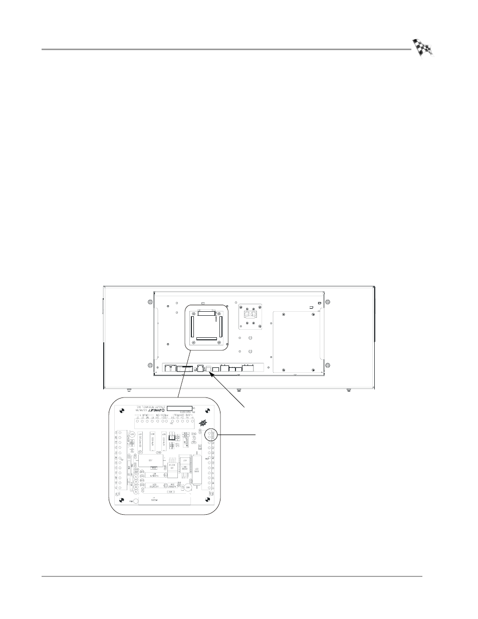
Attach the 4-pin connector to port P7 on the CPI board.
Figure 3-2: Route the Air Brake Cable
PD149
P7 on the
CPI board
brake wiring block
on breakout board