Ground hook installation – Dynojet 250iPX: Installation Guide User Manual
Page 82
In Ground Model 200iPX/250iPX Motorcycle Dynamometer Installation Guide
C H A P T E R 2
Ground Hook Installation
2-60
. . . . . . . . . . . . . . . . . . . . . . . . . . . . . . . . . . .
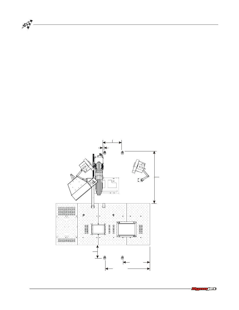
GROUND HOOK INSTALLATION
Using Figure 2-51 as a guide, place the ground hooks in a location that works best for
your dyno application.
You will need the following parts:
• 10111
Ground Hook/D-Ring (4)
• 10112
D-Ring Bracket (4)
• 36932100
Washer, 3/8", Splitlock, Steel (8)
• 37513200
Anchor, Redhead, 3/8" (8)
• DM150-002-007
Washer, 5/16", Flat (8)
• DM150-019-012
Bolt, 3/8-16 x 1", Hex (8)
1
Using the ground hook as a template, mark and drill each hole needed to secure
the ground hooks to the floor.
2
Install the Red Head anchors. Refer to Appendix A for installation instructions.
3
Secure each ground hook to the floor using two 3/8-16 x 1-inch hex bolts, two
5/16-inch flat washers, and two 3/8” lock washers.
Figure 2-51: Ground Hook Placement
6.10 cm
(2.40 in.)
64.52 cm
(25.40 in.)
standard carriage
172.21 cm (67.80 in.)
extended carriage
223.00 cm (87.80 in.)
145.54 cm
(57.30 in.)
43.69 cm
(17.20 in.)
87.12 cm
(34.30 in.)
PD142