Dynojet 250iPX: Installation Guide User Manual
Page 58
In Ground Model 200iPX/250iPX Motorcycle Dynamometer Installation Guide
C H A P T E R 2
Routing Cables
2-36
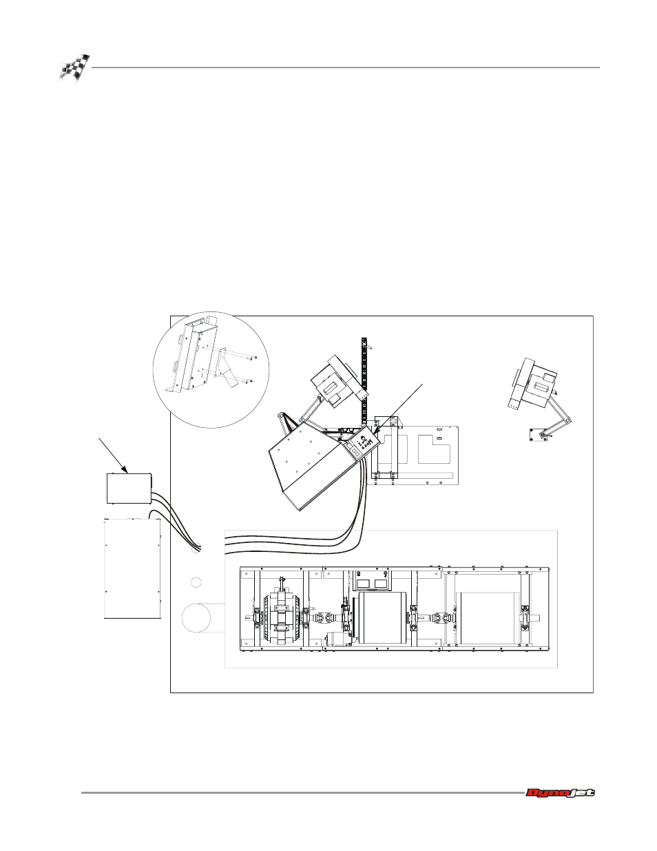
12 Secure the control panel to the monitor tray using two 8-32-inch screws.
Note: If you did not order a monitor tray, you will need to install the control pod
spindle on the bottom of your control panel using four 8-32 screws as shown in
the detail in Figure 2-28. Once installed, place the pin on the control panel into
the support arm where the monitor tray is.
13 Place the pendant in the slot on the control panel.
Note: If you plan on routing your cables through a zip tube refer to “Zip Tube” on
page 2-59 and skip the following steps.
14 Route the cable bundle along the support arms with service loops to allow
movement as shown below.
15 Using the provided cable clamps and 8-32-inch screws, attach the cable bundle to
the arms and the support arm. Adjust the service loops to allow for easy
movement of the monitor arms without pulling on the cables.
Figure 2-28: Install the Control Panel
PD122
control
panel
CPI
dyno
electronics
install control pod
spindle if you did not
purchase the monitor
tray