Dynojet 250iPX: Installation Guide User Manual
Page 63
I N S T A L L A T I O N
Routing Cables
Version 2
In Ground Model 200iPX/250iPX Motorcycle Dynamometer Installation Guide
2-41
R
OUTING
THE
P
ICKUP
C
ARD
AND
D
YNO
E
LECTRONICS
C
ABLES
1
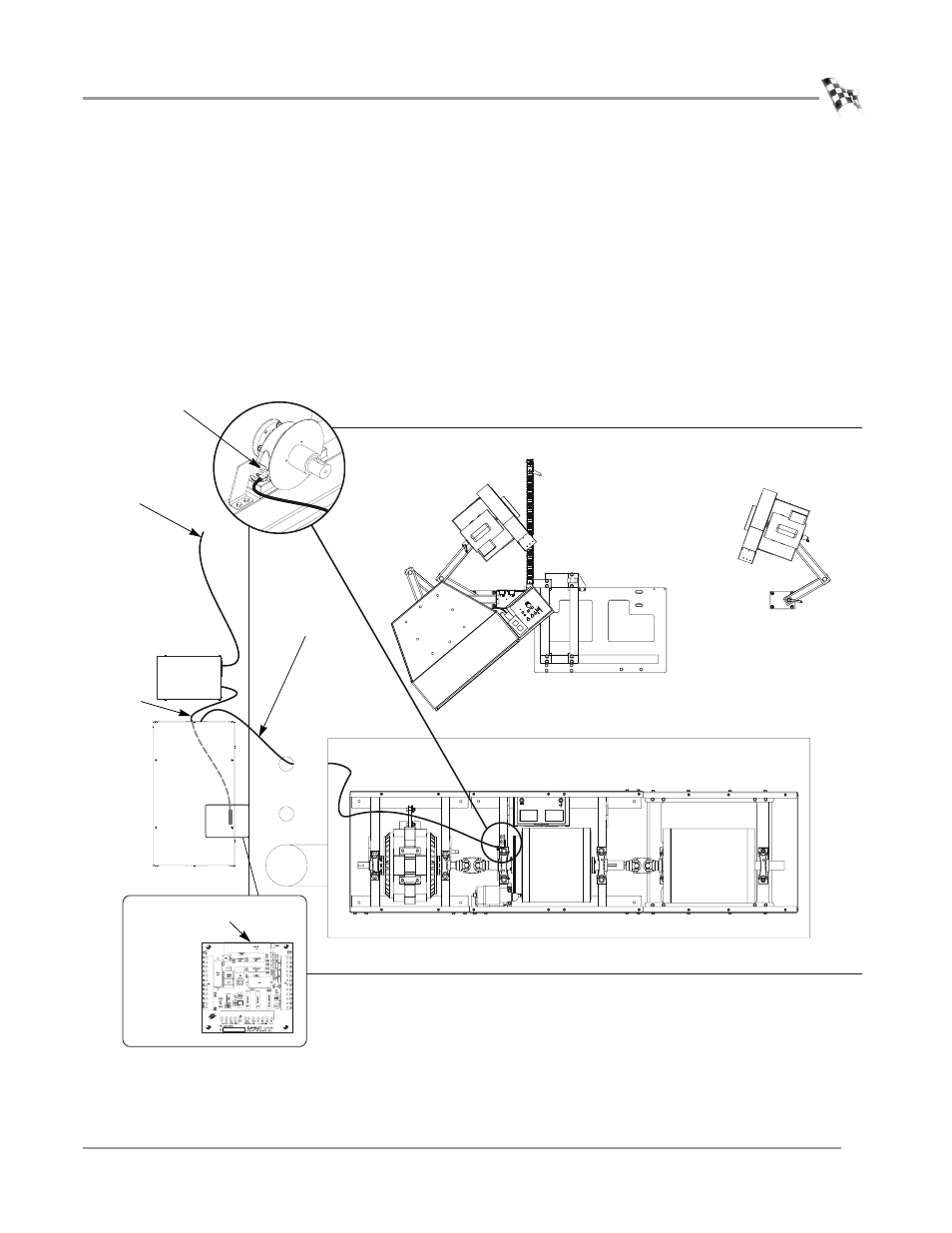
Route the pickup card cable (P/N 66953002) from the CPI through the designated
pit conduit and over to the pickup card. Attach the cable to the pickup card.
Note: Be sure to keep the power and communications cables in different pit
conduits.
2
Route the 25-pin cable (P/N 42924251) from the dyno electronics input/output
module to the Breakout board. Refer to Figure 2-35 for Breakout board location.
Refer to “Dyno Electronics” on page 1-10 for the 25-pin cable location.
3
Route the 9-pin serial cable (P/N 42967090) from the dyno electronics CPU
Module to your computer. Refer to “Dyno Electronics” on page 1-10 for the
9-pin serial cable location.
Figure 2-33: Route the Pickup Card and Dyno Electronics Cables
PD126
pickup card
dyno
electronics
CPI
25-pin cable to
breakout board
9-pin cable to
computer
pickup card cable
25-pin
cable to
breakout
board