Eddy current brake installation, Unpacking the eddy current brake – Dynojet 250iPX: Installation Guide User Manual
Page 31
I N S T A L L A T I O N
Eddy Current Brake Installation
Version 2
In Ground Model 200iPX/250iPX Motorcycle Dynamometer Installation Guide
2-9
. . . . . . . . . . . . . . . . . . . . . . . . . . . . . . . . . . .
EDDY CURRENT BRAKE INSTALLATION
This section will walk you through removing the eddy current brake (or retarder)
from the crate and attaching the brake to your dyno. To route and wire the
temperature sensor cable and the theta controller to the Breakout board refer to
“Routing the Eddy Current Brake, Battery, and Dyno Power Cables” on page 2-39 and
“Wiring the Breakout Board” on page 2-43.
You will need to provide equipment capable of lifting the eddy current brake off the
crate and into position in your dyno room. You will also need a pair of straps. Dynojet
recommends using continuous nylon loop style straps.
To prevent possible injury, unplug all power cords and disconnect the battery.
You will need the following parts:
• 62919004
Eddy Current Brake
• 37620622
Woodruff Key, 3/8 x 1-3/8"
• 62240070
Driveline Assembly
U
NPACKING
THE
E
DDY
C
URRENT
B
RAKE
1
Remove the four bolts securing the brake to the crate.
2
Remove the retarder connector plates, if present.
3
Place the ends of a nylon loop strap through the lifting eyes on either side of the
brake and hook onto the shaft.
4
Using a forklift, lift the eddy current brake from the crate and place the brake in
the pit near the drum module making sure not to hit the driveline assembly.
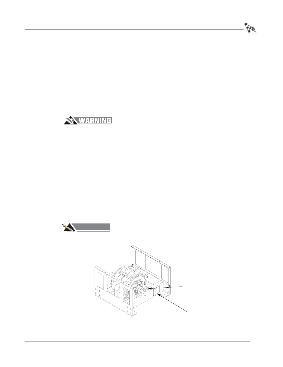
5
Record the eddy current brake number on the inside cover of this manual.
#
RECORD
Be sure you record the eddy current brake number on the inside cover of this
manual.
Figure 2-4: Record the Eddy Current Brake Number
eddy current brake number
lifting eye