5 mounting the robotic arm – Metrohm 789 Robotic Sample Processor XL User Manual
Page 36
2.2 Instrument setup
28
Metrohm Sample Processor, Installation
Swing
Head
Connecting to the Swing Head connection socket
Lead the connection cable of the 786 Swing Head through the guide
chain of the tower and connect the mini-DIN plug of the Swing Head
connection cable to the Swing Head socket on the rear panel of the
tower.
Configuring the Swing Head and robotic arm
As each type of robotic arm has its own dimensions, it is essential to
adapt the Swing Head setup settings to suit the particular type of ro-
botic arm.
The necessary alterations are made in the setup dialog, see Section
3.13. The individual settings affect:
• Swing offset (default: 0°)
• Max. swing angle (default: 84°)
• Swing radius (=length of robotic arm, default: 110 mm)
• Swing direction (default Tower1: –, default Tower 2: +)
The setup dialog of the Sample Processor is opened by pressing the
is given in Section 3.13. Details about the individual settings and types
of robotic arm can be found in the Instructions for Use of the 786 Swing
Head.
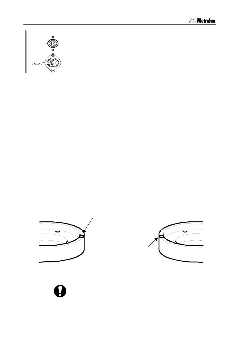
2.2.5 Mounting the robotic arm
Certain robotic arms can, depending on the model, be mounted so that
they swing to the right or the left. During the mounting process the loca-
tion of the limiting screw of the robotic arm must be taken into account.
Fig. 12 Robotic arm with limiting screw
Swing-right mounting means: The robotic arm can swing from the
zero-axis (center of the rack) to the right, as seen from the front. The
swing direction has to be set to '
–'.
Limiting screw
(for swing-right mounting)
Limiting screw
(for swing-left mounting)