5 connections, 1 sensors of the sample processor – Metrohm 789 Robotic Sample Processor XL User Manual
Page 17
1.5
Connections
Metrohm Sample Processor, Introduction
9
1.5 Connections
The electrical connections are the same for all models of the Metrohm
778/789 Sample Processor series.
W A R N IN G - F ir e H az ar d -
w ith th e sa m e t yp e a n d ra tin g o f fu se
F o r c o n t in ue d pr o tec tio n r e p lace o n ly
M a d e b y M e tr o h m
H e r is a u S w itz e rl a n d
S : 11 5 V A U : 10 0 - 2 40 V
f: 50 - 6 0 H z
R S 2 3 2
M S B 1
M S B 3
M S B 2
P o w e r
K e y b o a r d
R e m o te
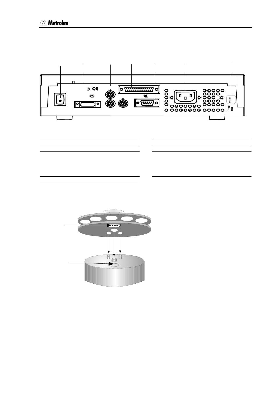
Fig. 4 Connection strip
20 Mains switch
24 Serial RS232 connection (9-pin)
21 Keyboard connection
25
Mains connection
22 MSB connections MSB1 … MSB3
Metrohm Serial Bus
Connection of dosing devices and stir-
rers
26
Type plate
23 Remote connection (25-pin)
1.5.1 Sensors of the Sample Processor
Fig. 5 Magnet sensor for rack code
Rack sensor
The magnet sensor for recognizing
the individual rack code is located be-
neath the turntable of the Sample
Processor. The magnet code of a
rack can only be read in when the
rack is in the initial position. The mag-
net holder must be positioned directly
above the sensor.
For this reason the Sample Processor
should be initialized each time that a
rack is changed with the
key.
20
21
22
23
24
25
26
Magnet
sensor
Magnet holder