Direction control – Rockwell Automation 20B PowerFlex 70, PowerFlex 700 Reference Manual User Manual
Page 91
Direction Control
Rockwell Automation Publication PFLEX-RM001H-EN-P - June 2013
91
PowerFlex 700 Firmware 3.001 (& later) Enhancements
Certain digital output enhancements have been included in firmware version
3.001 (and later) for the PowerFlex 700 Vector Control drive. These include:
•
Digital output control via Datalink
Parameter Controlled Digital Outputs
Enables control of the digital outputs through the Data In parameters.
Example
Digital Output 2 controlled by Data In B1
Setup
•
[Data In B1], parameter 302 = 379 ([Dig Out Setpt] as the Data In target)
•
[Digital Out2 Sel], parameter 384 = 30 "Param Cntl"
When Bit 1 of Data In B1 =1 Digital Out 2 will be energized.
Direction Control
Direction control of the drive is an exclusive ownership function. Thus only one
device can be commanding/controlling direction at a time and that device can
only command one direction or the other, not both. Direction is defined as the
forward (+) or reverse (–) control of the drive output frequency, not motor
rotation. Motor wiring and phasing determines its CW or CCW rotation.
Direction of the drive is controlled in one of four ways:
1.
2-Wire digital input selection such as Run Forward or Run Reverse (
).
2.
3-Wire digital input selection such as Forward/Reverse, Forward or Reverse
(
3.
Control Word bit manipulation from a DPI device such as a communications
interface. Bits 4 & 5 control direction. Refer to the
Logic Command Word
information in Appendix A of the PowerFlex 70 or 700 User Manual.
4.
The sign (+/-) of a bipolar analog input.
Direction commands by various devices can be controlled using the [Direction
Mask]. See
for details on masks.
for more detail
on the configuration and operating rules for direction control.
INPUTS & OUTPUTS
D
igi
tal
O
u
tpu
ts
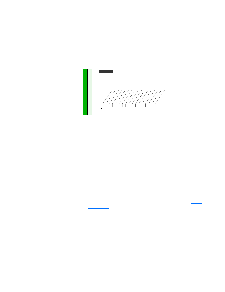
379
[Dig Out Setpt]
Sets the digital output value from a communication device.
Example
Set [Data In B1] to “379.” The first three bits of this value will determine the setting of [Digital
Outx Sel] which should be set to “24, Param Cntl.”
380
Vector v3
0
0
x
0
x
x
x
x
x
x
x
x
x
x
x
x
10
0
1
2
3
4
5
6
7
8
9
11
12
13
14
15
1
=Output Energized
0
=Output De-energized
x =Reserved
Bit #
Net DigOut1
Net DigOut2
Net DigOut3