Positive and negative limits, Output scaling – Rockwell Automation 20B PowerFlex 70, PowerFlex 700 Reference Manual User Manual
Page 145
Process PI Loop
Rockwell Automation Publication PFLEX-RM001H-EN-P - June 2013
145
The PI Integral Gain is entered in seconds. If the PI Integral Gain is set to 2.0
seconds and PI Error is 100.00% the PI output will integrate from 0 to 100.00%
in 2.0 seconds.
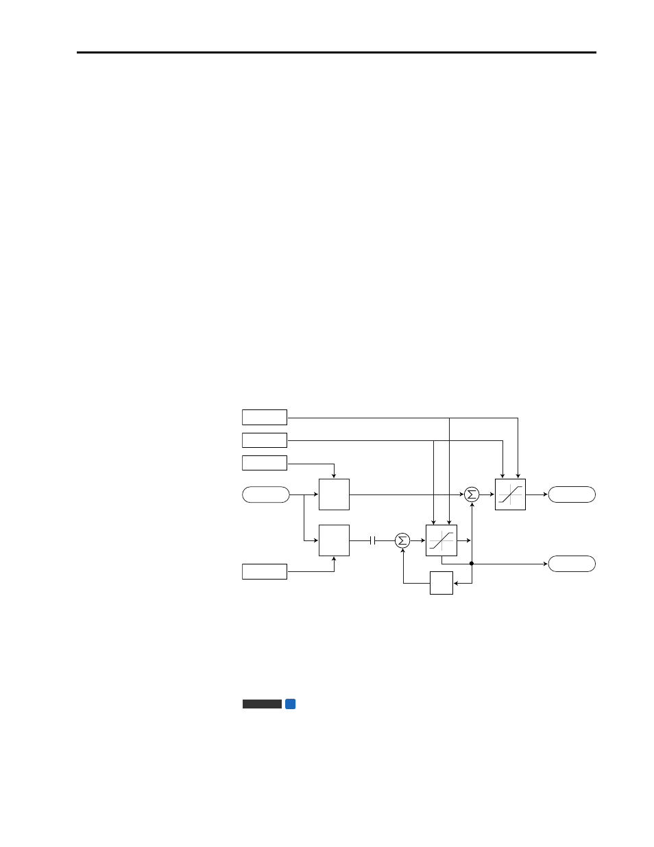
Positive and Negative Limits
The PI has parameters to define the positive and negative limits of the output PI
Positive Limit, and PI Negative Limit. The limits are used in two places; on the
integrator and on the sum of the Kp + Ki terms.
Providing an external source doesn't turn on Hold, the integrator is allowed to
integrate all the way to Positive or Negative limit. If the integrator reaches the
limit the value is clamped and the InLimit bit is set in the PI Status parameter to
indicate this condition.
The limits are entered in the range of ±100.00.
PI Positive Limit must always be greater than PI Negative Limit.
If the application is Process Control, typically these limits would be set to the
maximum allowable frequency setting. This allows the PI regulator to control
over the entire required speed range.
If the application is Process Trim, large trim corrections may not be desirable and
the limits would be programmed for smaller values.
Output Scaling
The output value produced by the PI is displayed as
±
100.00. Internally this is
represented by
±
32767 which corresponds to ±maximum frequency.
Output Scaling for Torque Trim
The output value from the Process PI loop, when in torque trim mode, is
displayed as +/–100% which corresponds to +/–100% of rated motor torque.
PI NegLmt
PI Kp
PI Ki
+
+
+
+
In Limit
PI PosLmt
*
*
PI_Status
.Hold
PI Error
Z
-1
PI Output
Vector
FV