Terminal designations & wiring examples – Rockwell Automation 20B PowerFlex 70, PowerFlex 700 Reference Manual User Manual
Page 29
Analog Inputs
Rockwell Automation Publication PFLEX-RM001H-EN-P - June 2013
29
Terminal Designations & Wiring Examples
Refer to the appropriate PowerFlex User Manual or “
Wiring and Grounding
Guidelines for Pulse Width Modulated (PWM) AC Drives,” publication
DRIVES-IN001 for I/O terminal designations and wiring examples.
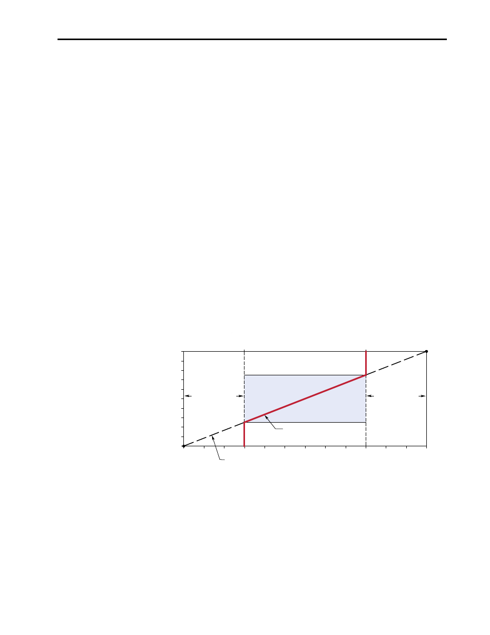
How [Analog Inx Hi/Lo] & [Speed Ref A Hi/Lo] Scales the Frequency
Command Slope with [Minimum/Maximum Speed]
Example 1:
Consider the following setup:
•
[Anlg In Config], bit 0 = “0” (voltage)
•
[Speed Ref A Sel] = “Analog In 1”
•
[Analog In1 Hi] = 10V
•
[Analog In1 Lo] = 0V
•
[Speed Ref A Hi] = 60 Hz
•
[Speed Ref A Lo] = 0 Hz
•
[Maximum Speed] = 45 Hz
•
[Minimum Speed] = 15 Hz
This operation is similar to the 0-10 volts creating a 0-60 Hz signal until the
minimum and maximum speeds are added. [Minimum Speed] and [Maximum
Speed] limits will create a command frequency deadband.
This deadband, as it relates to the analog input, can be calculated as follows:
1.
The ratio of analog input volts to frequency (Volts/Hz) needs to be
calculated. The voltage span on the analog input is 10 volts. The frequency
span is 60 Hz.
2.
Determine the frequency span between the Minimum and Maximum Speed
limits and Speed Ref A Hi and Lo.
Motor Operating Range
Command Frequency
15 Hz
45 Hz
60 Hz
0 Hz
Frequency Deadband
Slope defined by (Analog Volts)/(Command Frequency)
Frequency Deadband
7.5-10 Volts
0-2.5 Volts
[Speed Ref A Lo]
[Speed Ref A Hi]
10V
0V
[Analog In1 Hi]
[Analog In1 Lo]
[Maximum Speed]
[Minimum Speed]
10 Volts/60 Hz = 0.16667 Volts/Hz
[Speed Ref A Hi] – [Maximum Speed] = 60 – 45 = 15 Hz and . . .
[Minimum Speed] – [Speed Ref A Lo] = 15 – 0 = 15 Hz.