Block diagrams, Po werfle x 700vc, Bloc k diag rams – Rockwell Automation 20B PowerFlex 70, PowerFlex 700 Reference Manual User Manual
Page 44: Vector contr ol mode with speed contr ol
Block Diagrams
44
Rockwell Automation Publication PFLEX-RM001H-EN-P - June 2013
Block Diagrams
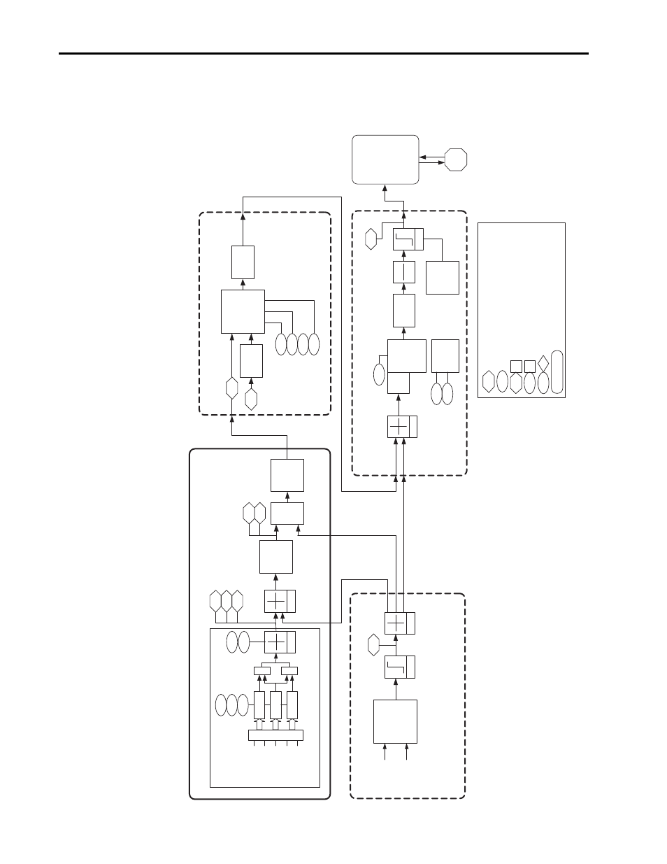
The following pages contain the block diagrams for the PowerFlex 700 Vector
Control drive.
Figure 1 PowerFlex 700VC Block Diagrams (1)
P
o
werFle
x 700VC
Bloc
k Diag
rams
Read Only P
a
ra
meter
Read /
Wr
ite P
a
rameter
Read Only P
a
ra
meter with Bit En
umer
ation
Read /
Wr
ite P
a
rameter with Bit En
umer
ation
Pro
vides additional inf
or
mation
Read
T
estpoint with Data Select
V
alue
PI Speed
Tr
im
PI Excl
Mode
PI Regulator
446
445
Kp Speed Loop
Ki Speed Loop
Lead Lag
Lead Lag
25
Speed Control - Regulator (1.0ms)
Speed Ref
erence
449
Speed Desired BW
23
447
Kf Speed Loop
T
orque
Selection
*, /, +
T
orque T
rim
Bus V
olt
& P
o
w
e
r
Regulator
Notch
Control
Dr
iv
e
& Motor
Protection
1
Flux
441
Mtr
T
or Cur Ref
T
orque Control (0.25ms)
Limit
88
Speed/T
orque Mod
Logic
1 0
0 1
161
162
Bus Reg Mode A
Bus Reg Mode B
Spd Reg In
V
ector
Control
Current
Processing
Motor
V
ector Contr
ol Mode with Speed Contr
ol
Linear
Ramp &
S Cur
v
e
Min/Max
Limits
Commanded Speed
2
Speed Ref Selection
Speed Ref A Sel
117
90
93
+
Analog 1/2
Enc/Pulse
MOP
Presets 1-7
DPI P
o
rt
1-6
Spd Ref A
Spd Ref B
Tr
im
S
O
U
R
C
E
S
+
Speed Ref B Sel
T
rim In Select
272
2
Commanded F
req
Dr
iv
e Ref Rslt
22
273
Ramped Speed
Dr
iv
e Ramp Rslt
+
Logic
1 0
0 1
Speed Control - Ref
erence (2.0ms)
Logic
1 0
0 1
100
108
Jog Speed 1
Jog Speed 2
PI Regulator
PI Ref
erence
PI F
eedbac
k
Limit
Process Control (2ms)
138
PI Output Meter
Logic
1 0
0 1
Speed
F
eedbac
k
(F
rom Encoder)