Signal loss – Rockwell Automation 20B PowerFlex 70, PowerFlex 700 Reference Manual User Manual
Page 27
Analog Inputs
Rockwell Automation Publication PFLEX-RM001H-EN-P - June 2013
27
Signal Loss
[Analog In 1, 2 Loss]
Signal loss detection can be enabled for each analog input. The [Analog In x
Loss] parameters control whether signal loss detection is enabled for each input
and defines what action the drive will take when loss of any analog input signal
occurs.
One of the selections for reaction to signal loss is a drive fault, which will stop the
drive. All other choices make it possible for the input signal to return to a usable
level while the drive is still running.
•
Hold input
•
Set input Lo
•
Set input Hi
•
Goto Preset 1
•
Hold Output Frequency
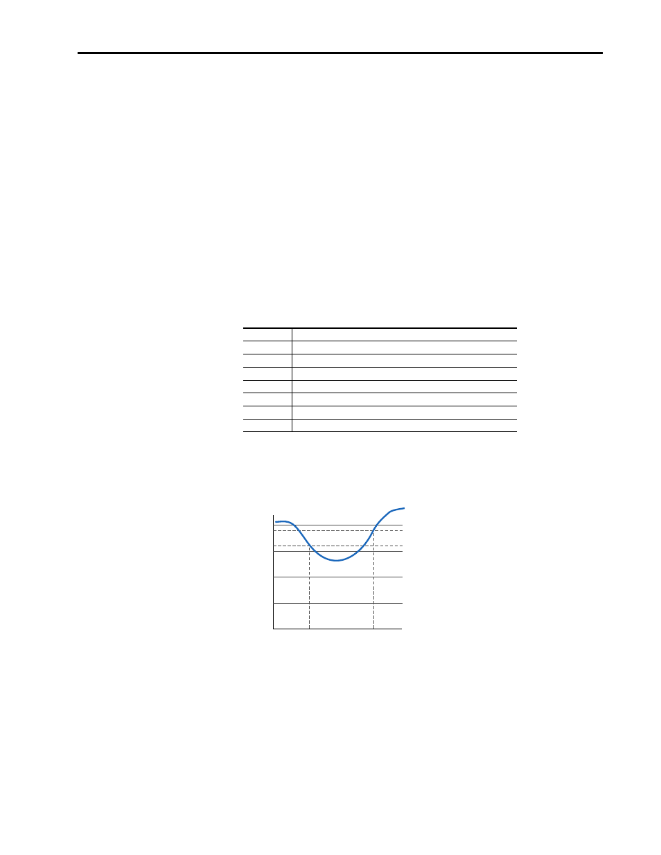
If the input is in current mode, 4 mA is the normal minimum usable input value.
Any value below 3.2 mA will be interpreted by the drive as a signal loss, and a
value of 3.8 mA will be required on the input in order for the signal loss
condition to end.
If the input is in unipolar voltage mode, 2V is the normal minimum usable input
value. Any value below 1.6 volts will be interpreted by the drive as a signal loss,
and a value of 1.9 volts will be required on the input in order for the signal loss
condition to end.
Value
Action on Signal Loss
0
Disabled (default)
1
Fault
2
Hold input (continue to use last frequency command.)
3
Set Input Hi - use [Minimum Speed] as frequency command.
4
Set Input Lo - use [Maximum Speed] as frequency command.
5
use [Preset 1] as frequency command.
6
Hold Out Freq (maintain last output frequency)
4 mA
3.8 mA
3.2 mA
Signal Loss
Condition
End Signal Loss
Condition