Rockwell Automation 20B PowerFlex 70, PowerFlex 700 Reference Manual User Manual
Page 164
Speed Control, Mode, Regulation & Vector Speed Feedback
164
Rockwell Automation Publication PFLEX-RM001H-EN-P - June 2013
original speed. Conversely, when the load is removed, the rotor speed increases
momentarily until the slip compensation decays to zero.
Motor nameplate data must be entered by the user in order for the drive to
correctly calculate the proper amount of slip compensation. The motor
nameplate reflects slip in the rated speed value at rated load. The user can enter
the Motor Nameplate RPM, Motor Nameplate Frequency, the Motor Nameplate
Current, Motor Nameplate Voltage, and Motor Nameplate HP/kW and during
commissioning the drive calculates the motor rated slip frequency and displays it
in [Slip RPM @ FLA]. The user can adjust the slip compensation for more
accurate speed regulation, by increasing or decreasing [Slip RPM @ FLA] value.
Internally, the drive converts the rated slip in RPM to rated slip in frequency. To
more accurately determine the rated slip frequency in hertz, an estimate of flux
current is necessary. This parameter is either a default value based on motor
nameplate data or the auto tune value. The drive scales the amount of slip
compensation to the motor rated current. The amount of slip frequency added to
the frequency command is then scaled by the sensed torque current (indirect
measurement of the load) and displayed.
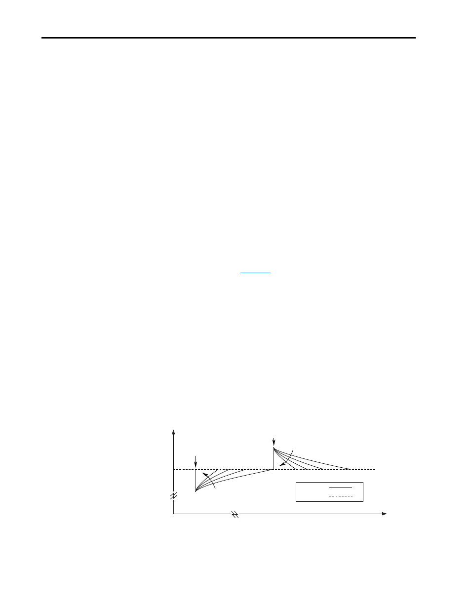
Slip compensation also affects the dynamic speed accuracy (ability to maintain
speed during “shock” loading). The effect of slip compensation during transient
operation is illustrated in
. Initially, the motor is operating at some
speed and no load. At some time later, an impact load is applied to the motor and
the rotor speed decreases as a function of load and inertia. And finally, the impact
load is removed and the rotor speed increases momentarily until the slip
compensation is reduced based on the applied load.
When slip compensation is enabled the dynamic speed accuracy is dependent on
the filtering applied to the torque current. The filtering delays the speed response
of the motor/drive to the impact load and reduces the dynamic speed accuracy.
Reducing the amount of filtering applied to the torque current can increase the
dynamic speed accuracy of the system. However, minimizing the amount of
filtering can result in an unstable motor/drive. The user can adjust the Slip Comp
Gain parameter to decrease or increase the filtering applied to the torque current
and improve the system performance.
Figure 34 Rotor Speed Response Due to Impact Load and Slip Com Gain
Time
Speed
0
0
Impact Load
Applied
Impact Load
Removed
Increasing Slip
Comp Gain
Increasing Slip
Comp Gain
Rotor Speed
Reference